background image

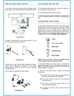
DRAIN CLAMP INSTALLATION

1) The drain clamp assembly should be installed above 
the trap and on the vertical or horizontal tailpiece (Fig. #5)

2) Mark the hole position on the pipe and drill a ¼” hole 
through one side of the pipe (Fig. #6).

3) Make sure to align drain saddle to drilled hole. Attach 
drain  clamp  to  drain  pipe  and  tighten  the  two  screws 
evenly (Fig #7). NOTE: The center hole on the sponge 
must be removed.

4) Connect the red tubing to the drain clamp.

POSITIONING THE SYSTEM

CONNECTING THE SYSTEM

1) The head assembly will stand up in the sink cabinet or 
can be hung on screws provided.

2) The storage tan k may be laid on its side.

3)The head assembly and/or storage tank maybe placed 
up to 15 feet from the point of use with nominal pressure 
loss.

1) Compression fittings may be found on the water supply 
adapter and the faucet. To make the connections, slide a 
compression  nut  onto  the  tubing  (Fig.  #8),  slip  a  white 
plastic  sleeve  onto  the  tubing  with  the  beveled  end 
towards the end of the tubing, insert a brass insert into the 
tubing, bottom the tubing into the fitting, slide the nut up 
and tighten with a wrench. 

DO NOT OVER TIGHTEN

.

NOTE:  Do  not  use  brass  sleeves  on  plastic  tubing, 
use only plastic sleeves on plastic tubing.

1) The plastic fitting on the drain clamp is connected by 
slipping  the  plastic  nut  onto  the  tubing,  insert  brass  or 
plastic  insert  into  the  tubing,  bottom  the  tubing  into  the 
fitting and tighten finger tight.

2)  Use  the  color  coded  tubing  to  make  the  following 
connections:

      A) The tubing connects the water supply adapter to the
           first clear housing of the head assembly.

      B) The  tubing  connects  the  faucet  to  the  outlet  side
            of the post carbon.

    C)  The  tubing  connects  the  storage  tank  to  the
            inlet side of the post carbon.

      D)  The  tubing  connects  the  drain  clamp  to  the  R/O
            membrane.

Summary of Contents for RO5

Page 1: ...Treat your body to pure goodness with Apex filtered water MODEL RO 5 INSTRUCTION MANUAL APEXWater Filters pure water in every drop ...

Page 2: ...ater supply adapter model SV 1 NOTE The drinking water system must be connected to the COLD water supply only 1 Turn off the cold water supply to the sink faucet by locating the round or oblong handle on the right side of the sink cabinet and turning clockwise until the water supply is off NOTE If the cold water shut off valve fails to turn off the water the house water supply can be turned off at...

Page 3: ...ing sure it will have a neat water fall pattern and that the faucet stud will be accessible from below once the hole is completed 3 For Porcelain Sink Before starting the drill motor apply firm downward pressure on the bit until a crunching occurs This will help keep the drill bit from moving when TAPPING INTO THE COLD WATER LINE DRILLING THE HOLE FOR THE FAUCET 4 For Stainless Steel Sink Before u...

Page 4: ...upply adapter and the faucet To make the connections slide a compression nut onto the tubing Fig 8 slip a white plastic sleeve onto the tubing with the beveled end towards the end of the tubing insert a brass insert into the tubing bottom the tubing into the fitting slide the nut up and tighten with a wrench DO NOT OVER TIGHTEN NOTE Do not use brass sleeves on plastic tubing use only plastic sleev...

Page 5: ...f you have any difficulties with the installation or require additional information on your unit please consult with our factory technicians We thank you for purchasing our RO 5 50P Reverse Osmosis unit Your high quality processed drinking water In order to maintain this high quality water it is important that scheduled maintenance be followed 1 Sediment Pre filter The pre filter protects the syst...

Page 6: ...s 4 Check the saddle valve at the water supply adapter is turned all the way counterclockwise for feed water and that there is no restrictions along the green tubing 5 Check for restrictions along the blue and yellow tubing and the storage tank ball valve handle should be parallel open to the valve body 6 Check the pre filter if it has a heavy dirt load it can restrict water flow to the system Cha...

Reviews: