10
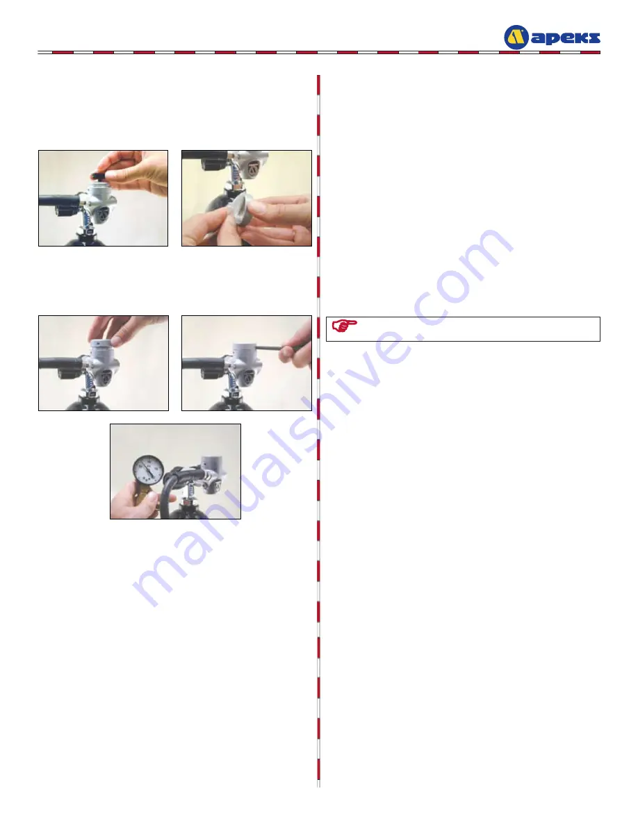
1. With the first stage still pressurized,
insert the hydrostatic
transmitter (4) into the dry chamber. Press the hydrostatic
diaphragm () into the end cap (1).
. Thread the end cap (1) onto the dry chamber until hand tight.
Using the pin spanner (pn AT0), tighten the end cap until
snug. Recheck the MP to confirm it has not changed.
. Close the cylinder valve and depressurize the regulator. Re-
move the test gauge and reinstall the blanking plug.
FINAL ASSEMBLY
NOTE: Do not confuse bubbles from trapped air with a true leak. If
there is an air leak, bubbles will come out in a constant stream.
. Assuming there are no leaks, close the cylinder valve and
depressurize the regulator. Remove the first stage from the
cylinder valve and secure the dust cap in place.
THIS CONCLUDES THE SERVICE PROCEDURES
FOR THE FSR/FST FIRST STAGE.
External Leak Test
1.
After disconnecting the MP test gauge from the first stage,
connect the first stage to a scuba cylinder filled to approxi
-
mately 000 psi (06 bar). Slowly open the cylinder valve to
pressurize the regulator and submerge the entire system in a
test tank of clean water.
. Observe any bubbles arising from the submerged regulator
over a one minute period. The recommended time is neces-
sary due to slower bubble formation that occurs in smaller
leaks. Bubbles indicate a leak, this would require the system
to be disassembled at the source to check sealing surfaces,
assembly sequence and component positioning in order to cor-
rect the problem(s). If any bubbles are visible, refer to
Table
1: Troubleshooting Guide, p. 11.
FINAL TESTING PROCEDURES


