background image

Apeks Supercritical: The Duplex

 Installation Manual 

 Revision Date 04/11/2019 


2.1.1. 

Diaphragm Compressor


Main Control 

Enclosure 

HMI 

CO

2

 Outlet 


CO

2

 Inlet 


Junction Box 


Regenerative 

Heat 

Exchangers


Fork Pockets


Figure 2:

 Front view of standard layout (Duplex 2000-20Lx20LDU) 

Figure 3:

 Diaphragm Compressor 

Summary of Contents for 2000PSI THE DUPLEX

Page 1: ...E TO FOLLOW THE SET UP AND OPERATION PROCEDURE PROVIDED IN WITHIN THIS MANUAL MAY VOID THE EXTRACTION SYSTEM S WARRANTY Apeks Supercritical 150 Commerce Blvd Johnstown OH 43031 740 809 1160 service apekssupercritical com www apekssupercritical com Scan this QR code to get the most recent version of the installation instructions ...

Page 2: ...s 8 2 3 Electrical Requirements 8 2 4 Facility Requirements 10 3 When the System Arrives 10 3 1 Receiving the Crates 10 3 2 Unpacking Instructions 11 3 3 Set Up and Assembly 15 3 3 1 Layout Footprint 15 3 3 2 Coolant Line and Chiller Setup 15 3 3 3 CO2 Connections 16 3 3 4 CO2 Vent Connections 18 3 3 5 Air Connection 18 3 3 6 Electrical Connections 20 3 3 7 Chillers 21 3 3 8 Email Alerts and Softw...

Page 3: ...e safe operations WARNING Opening a vessel under pressure can result in a rapid release of pressure and ejection of material from inside the vessel DO NOT ATTEMPT TO OPEN A VESSEL UNDER PRESSURE Always make sure a vent path for the vessel is opened and the corresponding pressure gauge reads zero prior to loosening the vessel closure WARNING Subcritical and Supercritical CO2 systems are designed to...

Page 4: ...l 4 Revision Date 04 11 2019 2 Before the System Arrives 2 1 System Overview Duplex Diaphragm Compressor Separator Chiller Extractor Chiller Extractor Vessel Stand Separator Vessel Stand Figure 1 Overhead view of standard layout Duplex 2000 20Lx20LDU ...
Page 5: ...al 5 Revision Date 04 11 2019 2 1 1 Diaphragm Compressor Main Control Enclosure HMI CO2 Outlet CO2 Inlet Junction Box Regenerative Heat Exchangers Fork Pockets Figure 2 Front view of standard layout Duplex 2000 20Lx20LDU Figure 3 Diaphragm Compressor ...
Page 6: ...ritical The Duplex Installation Manual 6 Revision Date 04 11 2019 2 1 2 Extractor Vessel Stand Extractor B Extractor A Temperature Control Heat Exchanger Flow Switch Figure 4 Extraction Vessels on Extraction Stand ...

Page 7: ...ation Manual 7 Revision Date 04 11 2019 2 1 3 Separator Vessel Control Stand Bank 1 Bank 2 E Stop Evacuation Valve Vent Valve Flow Switch Collection Cup Water Valves Cup Lift Control Panel Mount Figure 5 Extraction Vessels and Control Panel ...

Page 8: ...Chiller Air Compressor Max Pressure psi 2000psi 2000psi 2000psi 100psi 100psi 125psi Operating Temperature F 40 F 160 F 40 F 160 F 75 F 250 F 20 F 150 F 20 F 150 F 60 F 80 F Dimensions in WxDxH 58x42x77 53x36x84 74x37x68 25x34x53 19x30x39 14x24x18 Weight lbs 1000 lbs 750 lbs 4500 lbs 500 lbs 450 lbs 80 lbs 2 3 Electrical Requirements Figure 6 Electrical Requirements for Duplex with two Indoor Chil...

Page 9: ...Apeks Supercritical The Duplex Installation Manual 9 Revision Date 04 11 2019 WARNING Do not Modify Power Connections Figure 7 Electrical Requirements for Duplex with one Outdoor Chillers ...

Page 10: ...able to be located in different rooms or area to isolate different portion of the process This modulation should be stated during the purchase process or additional costs and delays may occur 2 4 5 CO2 Vent Customer is responsible for running rigid tubing from system outlet to a safe vent location NOTE Vent lines should be rated to the pressure of the system x 035 or x 049 stainless steel tubing r...

Page 11: ...ternal damage If damage is found do not accept delivery from the shipping company without noting any damage on Proof of Delivery In addition call Apeks at 740 809 1160 to report damage and start the reporting process with the shipping company 3 2 Unpacking Instructions WARNING Heavy Components Do not attempt to lift without the proper equipment 3 2 1 Uncrating the Extractor Stand and Separator Con...

Page 12: ...ft to remove the stand from the skid and attach the four leveling feet to each stand See Figure 4 3 2 1 5 Once the system is on the ground use these feet to get the system level and then snug the jam nut against the stand to secure the feet Wood Tie Downs Jam Nut Figure 3 Wood Tie Downs Figure 4 Leveling Feet ...

Page 13: ...s and top of the shipping crate See Figure 5 3 2 2 2 Remove lag screw bolts that keep the pump attached to the skid 3 2 2 3 Carefully use a forklift to remove the pump from the skid and attach the four rubber vibration dampening feet to the four corners of the pump See Figure 6 Figure 5 Diaphragm pump on skid Figure 6 Vibration Dampening Feet ...

Page 14: ...chiller to the base 3 2 3 3 Use a forklift or the provided ramp to remove the chiller from the base 3 2 3 4 When chiller is in final location lock the wheels 3 2 4 Verifying Apeks Shipper Every Apeks machine is sent with a shipper that will contain quality control checklist and a packing slip Verify that all items on the packing slip example below have been received Contact Apeks if there are item...

Page 15: ...tch on the separator stand 3 3 2 1 3 Separator Stand to Chiller Inlet The hose on the chiller outlet will connect to the water valve without the flow switch on the separator stand 3 3 2 2 Extractor Coolant Loop The extractor coolant loop will incorporate the Extractor Chiller and the Extractor Vessel Stand 3 3 2 2 1 Chiller Outlet to Extractor Stand The hose on the chiller outlet will connect to t...

Page 16: ...sure to the operating pressure 3 3 2 3 6 As the pressure increases the reservoir level may decrease so top off as necessary 3 3 2 3 7 Once the chillers are up to pressure the extractor chiller is ready to run and can be turned off 3 3 2 3 8 The separator chiller loop will need separator bank 2 filled with fluid 3 3 2 3 8 1 Go to the manual screen and click the Fill Separator Bank 2 WATER button No...

Page 17: ...e line with compression fittings 3 3 3 3 Extractor Vessel Stand to Separator Vessel Stand These connections are 18 long stainless steel braided flexible lines with 3 8 compression fittings Connect 1 and 2 on the extractor stand to 1 and 2 on the separator stand respectively 1 2 Figure 9 Diaphragm Compressor to Extraction Vessel Figure 10 Extraction Vessel Stand to Separator Vessel ...

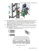
Page 18: ...d to the pressure of the system 3 8 x 035 or x 049 stainless steel tubing recommended Connection is a 3 8 Swagelok compression fitting 3 3 5 Air Connections There are over twenty five air operated ball valves that are used to control the CO2 flow path throughout the system These valves are controlled by an air manifold on the back of the control panel mount 3 3 5 1 Air Manifold The air manifold re...

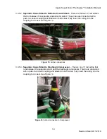
Page 19: ...coupling and labeled on both sides Fully insert the tubing into the coupling to connect See Figure 13 3 3 5 3 Separator Vessel Stand to Diaphragm Compressor There is one red airline that runs between the separator stand and the diaphragm compressor This line is connected with a push to connect coupling and labeled on both sides Fully insert the tubing into the coupling to connect See Figure 14 Fig...

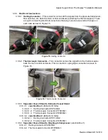
Page 20: ...m the thermocouples back the main control enclosure This connector is a plug style connection as seen in Figure 16 3 3 6 3 Separator Vessel Stand to Extractor Vessel Stand 3 3 6 3 1 Junction Box 3 Extractor B Side 3 3 6 3 1 1 Harting Connector 1214CBL1 3 3 6 3 1 2 Thermocouple Connector 1709CBL1 3 3 6 3 1 3 Thermocouple Connector 1809CBL1 3 3 6 3 2 Junction Box 2 Extractor A Side 3 3 6 3 2 1 Harti...

Page 21: ...s The wiring coming from the top of the motor starter will be terminated to the facility power 3 3 7 Chillers 3 3 7 1 Communication Cable Each chiller is connected to the main control enclosure by a 15 pin connector shown in Figure 18 The cable will be labeled EXT Chiller or SEP Chiller 3 3 7 2 Power The chiller is terminated to the facility power by customer supplied wiring terminated to the chil...

Page 22: ...ssages to a designated email and then this email will send messages to any person s phone numbers you decide to forward messages to 3 3 8 4 After connecting the system to the internet via an Ethernet cable and after the designated email for the system has been set up please go to http www apekssupercritical com customer support service request and submit a ticket with the systems information and a...

Page 23: ... your onsite training o Must be complete before scheduling training Print complete operational manual and have on site the day of training along with the chiller manual o Must be complete before scheduling training Apeks system and diaphragm compressor are unpacked and set up in its location of operation Refer to unpacking instructions in the installation manual o Must be complete before schedulin...

Page 24: ...ining via our website http www apekssupercritical com training o Onsite training is generally a four hour block of instruction that will go into detail the fundamentals of operation and maintenance of each component of the system 5 References YouTube Instructional Videos https www youtube com user ApeksSupercritical Apeks online store 740 809 1160 option 2 http apeksonlinestore com Software Update...

Page 25: ...Apeks Supercritical The Duplex Installation Manual 25 Revision Date 04 11 2019 6 Appendices 6 1 Appendix A System Layouts The Duplex 2000 20Lx20LDU Standard Layout ...

Page 26: ...Apeks Supercritical The Duplex Installation Manual 26 Revision Date 04 11 2019 The Duplex 2000 20Lx20LDU CGMP Layout ...

Page 27: ...Apeks Supercritical The Duplex Installation Manual 27 Revision Date 04 11 2019 The Duplex 2000 4x20LDU Standard Layout ...

Page 28: ...Apeks Supercritical The Duplex Installation Manual 28 Revision Date 04 11 2019 The Duplex 2000 4x20LDU with External Chiller Layout ...

Page 29: ...y 95 98 Phillip Screws 5 lb in 12 Large Motor Contactor Allen Screws 100 C72D10 53 lb in 13 Large Motor Contactor Phillips Screws 100 C72D10 13 lb in 14 Overload Relay Allen Screws 193 EEGE 40 lb in 15 Overload Relay Phillips Screws 192 EEGE 5 lb in 16 Micro 850 Power Supply 4 4 lb in 17 Micro 850 Terminal Strip 4 4 lb in 18 2080 TC2 2 21 lb in 19 2080 IF4 2 21 lb in 20 2080 IF2 2 21 lb in 21 HMI ...

Reviews: