
27
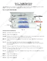
Part II: Trouble-Shoot Guide
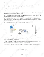
For Newly Installed RO System
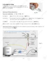
After installation, if you encounter any of the problems described below, please follow this guide to trouble-
shoot. In most cases, the problem is quickly solved by following this guide.
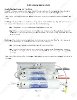
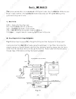
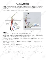
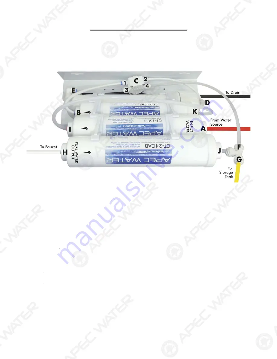
Non-Pump RO HEAD DIAGRAM
52+HDG3RLQWV,GHQWL¿FDWLRQ
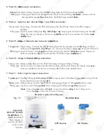
Point A
: Feed water inlet into Stage-1 filter
Point B
: Stage-2
filter’s
output
port .
Point C
: Automatic-Shut-Off (ASO) valve. For Permeate Pumped systems, the permeate pump replaces the
ASO valve, it serves both as a pump and an auto-shut-off valve.
Point D
: Stage-3 Membrane housing
inlet
port. Feed water from Stage-3 filter enters the Membrane at
this port.
Point E:
Check Valve. The filtered water from the Membrane passes through this Check Valve
before entering the storage tank. The Check Valve blocks the tank water from back-flowing into
the membrane.
Point F:
T-fitting on Stage-4 filter. This end of the T-fitting connects to the CLEAR pure water line.
Point G:
T-fitting on the Stage-4 filter. This other end of the T-fitting connects to the YELLOW pure water
line which goes to the tank’s valve.
Point H
: The
output end
of Stage-4 filter. Pure water leaves Stage-4 filter via this port, and flows onto the
dispensing faucet.
Point I
: Stage-1
filter’s
output
port.
Point J
: Stage-4
filter’s
input
port.
Point K
: Stage-2
filter’s
input
port.
Fig. 16
Stage 1
Stage 2
Stage 3
Stage 4
27
Part II: Troub
b
l
l
e
e-
S
S
hoot Guide
For Newly I
I
n
n
s
s
t
ta
a
l
l
l
ed RO System
y
y
Af
f
te
te
r
r in
in
st
st
al
a
lation, if you encounter any of
f
th
th
e pr
pr
ob
ob
l
lems described below, please
f
f
ol
ol
lo
low
w
th
this guide to trouble-
sh
sh
oo
oo
t.
t.
In most cases, the problem is q
q
ui
ui
ck
ckly
ly s
s
ol
l
ved by following this guide.
N
Non-Pump RO HEAD DIAGRAM
52+HDG3RLQWV,GHQWL¿FDWLRQ
Point A
: Feed water inlet into Stage-1 filter
Point B
: Stage-2 filter’s
output
port .
Poin
n
t
t
C
C
:
:
A
Automatic-Shut-Off (ASO) valve. Fo
Fo
r
r Pe
Pe
rm
rmeate Pumped systems, the perme
me
at
a
e pump replaces the
ASO valve, it serves both as a p
p
um
u
p
a
and an auto-shut-off valve.
Po
Po
i
int D
: Stage-3 Membrane housing
g
in
in
le
le
t
t
port. Feed water from Stage-3 fil
il
te
te
r
r
en
en
t
ters the Membrane at
this port.
Point E:
Check Valve. The filter
red
ed water from the Membrane pas
s
se
ses
s
th
thro
ro
ugh this Check Valve
VV
before enterin
n
g
g
th
the
e
st
storage tank. The Check Valve bloc
ks
ks
t
the
he
t
ta
ank water from back-flowing into
the membrane
e
.
.
Point F:
T-fitting on Stage-4 filter. This end of the T-fitting connects to the CLEAR pure water line.
TT
Point G:
T-fitting on the Stage-4 filter. This other end of the T-fitting connects to the YELLOW p
pur
ur
e
e
w
water
TT
line which goes to the tank’s valve.
Point H
H
: The
output end
of Stage-4 filter. Pur
ure
e
wa
water leaves Stage-4 filter via this por
r
t,
t,
a
and
nd flows onto the
dispensing faucet.
Po
Po
in
in
t
t I
I
:
Stage-1 filter’s
output
port.
.
P
Point J
:
Stage-4 filter’s
input
por
or
t.
t.
Point K
: Stage-2 filter’s
inpu
put
t
p
p
or
or
t.
+HDG 3RLQWV ,GHQWL¿FDWLRQ
Fig. 16
Stage 1
Stage 2
Stage 3
Stage 4
4
Summary of Contents for Ultimate RO-QUICK90
Page 2: ......


