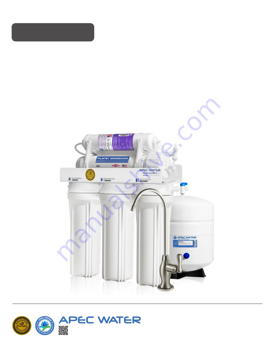
ULTIMATE
REVERSE OSMOSIS SYSTEM
RO-PH90 INSTALLATION
INSTRUCTION
& OWNER’S MANUAL
All Rights Reserved © APEC Water Systems
www.FreeDrinkingWater.com
Ver 2.3
Page 1: ...ULTIMATE REVERSE OSMOSIS SYSTEM RO PH90 INSTALLATION INSTRUCTION OWNER S MANUAL All Rights Reserved APEC Water Systems www FreeDrinkingWater com Ver 2 3...
Page 2: ......
Page 3: ...em flow diagram page 24 Input water pressure most important factor page 25 Tank volume delivery pressure page 25 26 Misc topics page 26 4 Trouble shoot Guide RO Head diagram page 28 Air bubbles page 2...
Page 4: ...nt avoid exposure to hot and cold weather or under direct sunlight General Installation Operation Maintenance Requirements Installation needs to comply with state and local laws and regulations System...
Page 5: ...Storage tank Installation kit includes 1 Feed water adaptor 3 8 1 2 with needle valve kit 1 Drain saddle for waste water 2 Color tubing 1 4 1 Tank s Ball Valve 2 Wrenches for opening filter and Membra...
Page 6: ...stage filter 6 Carbon block pre filter and housing 2nd stage filter 7 Carbon block pre filter and housing 3rd stage filter 8 Storage tank 9 Tank ball valve 10 ASO Automatic Shut Off valve 11 Check val...
Page 7: ...into the 1st stage housing on the right Put the APEC Carbon filter 23 CAB10 into the 2nd stage housing in the middle Put the APEC Carbon filter 23 CAB10 into the 3rd stage housing on the left 2 See Fi...
Page 8: ...treat both hard and soft water and can handle incoming TDS levels up to 2 000 ppm Fig 4 Step 1 Feed Water Connection The RO system must be connected to the COLD water supply only 1 Locate the Cold wa...
Page 9: ...our pipe has a 1 2 Connection By attaching the 1 2 x 3 8 converter B to the Male end of the water supply adapter A you now have a 1 2 Male and Female water supply adapter Fig 4C If your pipe has a 3 8...
Page 10: ...e shut off valve the same way as described above Option Connection Point See Fig 5F The feed water adapter can also be installed between the riser tube and faucet shank Loosen nut and separate cold wa...
Page 11: ...se screw the metal compression nut with the red tubing pushed all the way into the needle valve then use a wrench to fully tighten this connection Fig 5E Fig 5F 4 Needle Valve See Fig 5D Screw the Nee...
Page 12: ...the drain line as low as possible above the trap or on the horizontal tailpiece 2 Select the location of the hole and drill a 1 4 hole through one side of the drain pipe then put the self adhesive bla...
Page 13: ...mount the RO faucet there Remember to plug up the outlet under the main faucet If the spray hose uses a diverter at the base of the spout be sure to remove it to avoid trouble later on c Hanging fauce...
Page 14: ...age 12 2 Make sure the tube insert is pushed all the way into the tubing Fig 9C Page 12 3 Make sure the tubing is inserted inside the faucet stem at least 1 4 deep while screwing the compression nut F...
Page 15: ...m The main system can stand in the sink cabinet No need to mount the system to the wall If you prefer to mount the system to the wall please make sure it can be taken down easily for filter replacemen...
Page 16: ...wn the collet ring pull out the end plug with your other hand Only the plug will slide out from the connection See Fig 10C Depending on your system model there will be 2 types of protective end plugs...
Page 17: ...Point P to Z Connect product water from 6th stage output to RO faucet Clear tubing Drain line to W Connect drain water from 4th stage membrane to drain outlet Black tubing Fig 11 Fig 10E To Disconnect...
Page 18: ...t locations 1 Point Z Faucet connection Tubing color Clear tubing The tubing already attached into RO faucet no installation needed Option Faucet comes without tubing attached Tubing color Clear tubin...
Page 19: ...the Clear tubing into the QC fitting No Inserts Sleeves or Nuts are needed to secure the connection No Teflon tape needed here 6 Point G Stage 5 5 TCR QC filter s T fitting connection Tubing color Yel...
Page 20: ...y If you want the RO to feed your ice maker fridge only you should still connect the RO faucet as a 2nd outlet This allows you to drain the tank flush new filters through the faucet rather than throug...
Page 21: ...he Reverse Osmosis System End Installation Section Step 7 System Start Up 1 Turn on feed water Slowly turn on your Cold water supply Open the Needle Valve turn counter clockwise to allow the raw water...
Page 22: ...years It s best to replace this filter when 5 TCR QC replacing the stage 4 membrane Stage 6 Mineral Filter Replace every 6 12 months FI PHPLUS QC Important It is important to change the 3 pre filters...
Page 23: ...nd Turn ON the tank ball valve 7 Check for leaks How to Replace Stage 4 Membrane 1 Turn OFF the cold water supply to RO system Turn OFF tank ball valve Turn on RO faucet lever briefly to relief the bu...
Page 24: ...event contamination NOTE Only this filter change needs bleach sanitizing Do not apply chlorine bleach in any way to Membrane for it will damage the membrane 4 Connect New Filter See Fig 14C Attach the...
Page 25: ...square against the fitting With the collet held in this position the tube can be removed Once the outlet tubing is disconnected please remove inlet tubing at Point O Remove old filter and discard 3 Th...
Page 26: ...roblems with non pump systems page 27 How to test your water pressure page 27 Premature membrane failure page 27 Part II Trouble shoot Guide RO Head diagram page 28 Air bubbles page 29 No water at dis...
Page 27: ...inants PPM Parts Per Million unit used to measure TDS level TDS Meter A digital meter for measuring the TDS level in the water 2 Flow Diagram for 6 Stage RO System Fig 15 below shows how water flows t...
Page 28: ...be about 3 10 of your Tap water s TDS This is a normal range For example Your Tap water s TDS 100 ppm Your Product water s TDS should read within 10 of 100ppm 10ppm This means that with 100 ppm input...
Page 29: ...es See chart below for 4 gallon tank 4 gallon tank s delivery pressure 3 0 gallon 50 psi output delivery pressure pressure inside tank 2 5 gallon 36 psi 2 0 gallon 24 psi 1 5 gallon 18 psi 1 0 gallon...
Page 30: ...em out 12 Premature Membrane Failure There are 4 common causes that lead to premature membrane failure 1 Failing to replace the 3 pre filters as frequently as needed If you re on city water The over d...
Page 31: ...let port Feed water from stage 3 filter enters the Membrane at this port Point E Check Valve The filtered water from the Membrane passes through this Check Valve before entering the storage tank The C...
Page 32: ...o C2 OUT Check Valve Clear tubing point E is connected to C3 5th stage Tee inlet Clear tubing point F is connected to C4 Fig 17 1 Air Bubbles Lots of Air bubbles in cup or bottle when filling It is qu...
Page 33: ...te pump to system Low water temperature below 77 degree F Increase house water pressure or add pump to com pensate for low cold water temperature Claimed GPD The claimed gallon per day GPD flow rate f...
Page 34: ...onnect the Yellow line from the tank s valve A stream of filtered water will trickle out of the Yellow line Let the water trickle freely for about 1 minute then Catch some water here and do a TDS test...
Page 35: ...reducing input water pressure to RO Check and fix feed water valve make sure it is opened fully to allow maximum pressure to RO Stages 1 2 3 pre filters partially clogged reducing the input water pre...
Page 36: ...ter bills To test if your RO system is shutting down normally please follow the steps below Draw 3 4 glasses of water from spigot RO will start making water to fill tank Turn OFF the blue tank ball va...
Page 37: ...air bubbles being trapped in the Check Valve during installation See check valve on Fig 17 point E Page 29 To purge air from the check valve do as follows Step 1 Close the tank s valve Step 2 Tilt th...
Page 38: ...o the fitting port tightly Hook Up 1 Please connect each tubing to your RO system and drain outlet as follows Blue 1 4 tubing Connect the 1 4 Blue line from the Air Gap faucet to the RO s 1 4 Output C...
Page 39: ...ystem will discharge through the 1 4 RED line to the Air Gap faucet The drain water will then flow back down the 3 8 BLACK drain water line of the Air Gap faucet to your drain pipe Pure water output f...
Page 40: ...nditions of Validity of this Limited Product Warranty Even though the Product has extremely high endurance for operating conditions such as pH maximum TDS temperature and opti mum water pressure THIS...
Page 41: ...whatsoever as to the result of the use of the product purchased whether used singularly or in combination with any other products or substances No claim by the buyer owner of any kind including claim...
Page 42: ......
Page 43: ......
Page 44: ...ineering Corp 1320 S Johnson Drive City of Industry CA 91745 For questions or comments please visit our website at www FreeDrinkingWater com For technical support contact us at Techsupport freedrinkin...