


12345678901234567890123456
12345678901234567890123456
12345678901234567890123456
12345678901234567890123456
12345678901234567890123456
12345678901234567890123456
12345678901234567890123456
12345678901234567890123456
12345678901234567890123456
12345678901234567890123456
12345678901234567890123456
12345678901234567890123456
12345678901234567890123456
12345678901234567890123456
12345678901234567890123456
12345678901234567890123456
12345678901234567890123456
12345678901234567890123456
12345678901234567890123456
12345678901234567890123456
12345678901234567890123456
12345678901234567890123456
12345678901234567890123456
12345678901234567890123456
12345678901234567890123456
12345678901234567890123456
1234567890123456789012345
1234567890123456789012345
1234567890123456789012345
1234567890123456789012345
1234567890123456789012345
1234567890123456789012345
1234567890123456789012345
1234567890123456789012345
1234567890123456789012345
1234567890123456789012345
1234567890123456789012345
1234567890123456789012345
1234567890123456789012345
1234567890123456789012345
1234567890123456789012345
1234567890123456789012345
1234567890123456789012345
1234567890123456789012345
1234567890123456789012345
1234567890123456789012345
1234567890123456789012345
1234567890123456789012345
1234567890123456789012345
1234567890123456789012345
1234567890123456789012345
1234567890123456789012345
7032 SOUTH 196th - KENT, WA. 98032 - (206) 872-0141 / FAX (206) 872-8710
OPERATION / MAINTENANCE MANUAL
MODEL 50/75 AUGER
Page 5-3
V. MAINTENANCE (Continued...)
SHEAVES AND SPROCKETS - When mounting sheaves or sprockets,
the center of the load should be as close to the drive as possible.
Excessive overhung loading could result in early failures of bearing or
shaft. Refer to the factory or contact your local distributor for overhung
load ratings.
If any noticeable resistance is encountered when installing sheaves or
sprockets on shafts, inspect components for paint, burrs or imperfec-
tions and remove. Force fitting can easily damage gears, shafts and
bearings.
DIRECT COUPLED DRIVES - Inspect engine flywheel and flywheel hous-
ing to insure compliance to SAEJ620 and 617C. Clean flywheel face,
pilot bore and flywheel housing face and inspect for burrs, damaged
threads, etc. Remove and repair as required. Inspect drive plate and
flywheel housing on pump drive to insure acceptance by engine fly-
wheel and flywheel housing. Check drive plate fit on input shaft of
pump drive.This Must be an easy slip fit. Apply light film of Molykote G-
N or similar lubricant to pilot bore on flywheel and on internal splines of
drive plate. Install drive plate pilot into flywheel bore. Drive plate must fit
freely until driveplate contacts flywheel. Install lockwashers and bolts
through drive plate and into flywheel. Use lockwashers and bolts per
Engine Manufacturer specifications. Torque bolts to manufacturer speci-
fications. Re-check bolt length to insure drive plate is securely held to
flywheel. Too long a bolt will allow threads to “bottom out” in flywheel
resulting in a loose drive plate that could result in catastrophic failure.
Line up splines on input shaft of pump drive with internal splines on the
drive plate and insert until flywheel housing of pump drive is firmly
seated against flywheel housing on engine. Install bolts and lockwashers
and torque Per Engine Manufacturer specifications. Install pump(s) and
all required piping, hoses, etc. Fill drive to proper level with lubricant.
CLUTCH COUPLED DRIVES - Inspect engine flywheel and flywheel
housing to insure compliance to SAEJ620 and J617C. Clean flywheel
face, pilot bore and flywheel housing face and inspect for burrs, dam-
aged threads, etc. Remove and repair as required. Inspect drive ring,
clutch teeth and clutch housing on pump drive to insure acceptance by
engine flywheel and flywheel housing. Install pilot bearing on clutch
shaft. Apply force to the inner race of the pilot bearing during installa-
tion. Do not press pilot bearing all the way onto the shaft. Leave .06"
between front of pilot bearing and end of shaft. Install driving ring on
engine flywheel and secure with bolts per engine manufacturer’s
specifications. Install pump drive on engine, carefully aligning pilot bear-
ing in the flywheel bore and engaging clutch teeth with driving ring.
lnstall bolts and lockwashers and torque per engine manufacturer’s
specifications. Install pump(s) and all required piping, hoses, etc Fill
pump drive to proper with lubricant.
PREVENTATIVE MAINTENANCE - Keep shafts and vents clean to pre-
vent foreign particles from entering seals or gear case. Inspect periodi-
cally for oil leaks. Check drive mounting bolts for tightness, Check end
play in shafts. Noticeable movement might indicate service or parts
replacement is necessary.
HUB CITY has Sales Offices and a network of Industrial Power
Transmission Distributors that can serve your needs world wide.
Check the Yellow Pages or internet for one near you or contact the
factory sales office.
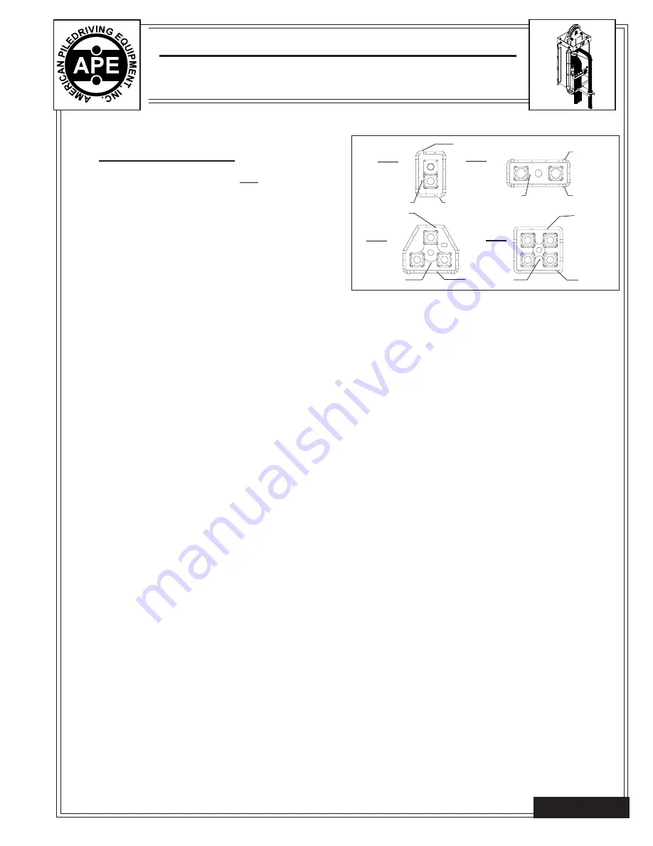
B
D
B
D
B
D
801, 751
763, 803
FIG.3
FIG.4
804
B
D
O
O
O
O
FIG.2
762, 772,
802
B-Breather
D-Drain
O-Oil Level
FIG.1
V-4. Gearbox Maintenance.
HUB CITY PUMP DRIVE MODELS - These Instructions apply to all HUB
CITY Pump Drives. Examples: 751F, 762C,763F, 772E, 801E, 802C.
803C, 804F.
LUBRICATION
ALL PUMP DRIVE UNITS ARE SHIPPED DRY. OIL MUST BE ADDED
PRIOR TO OPERATION.
All HUB CITY Pump Drives are splash lubricated. Figures 1A show
standard mounting positions. The quantity of lubricant required for op-
eration will vary depending on the speed and position the unit is mounted.
For most mounting positions approximately one-third of the cavity should
be filled.
BEFORE OPERATING: Remove breather plug (B Fig. 1A) and oil level
plug (O Fig. 1A). Note: Oil level plug is omitted on units equipped with oil
level sight gauge (801, 802, 803 and 804). Clean threads on removed
plugs and plug holes with degreaser. Fill unit with an approved lubricant
to oil level plug or until lube is visible in sight gauge. Install plugs securely
in gear case. Note: Plug with breather must be installed in uppermost
hole of pump drive.
The quantity of lubricant required for operation will vary depending on
the speed of operation. Input shaft speeds below 1000 RPM require
more oil to assure complete lubricant coverage. Speeds approaching
the 2400 RPM maximum may require somewhat less oil to reduce the
heat generated from splashing. Operating temperatures as high as
200°F will not damage the unit, providing proper lubrication is main-
tained.
For operation in ambient temperatures between 40°F and 1000°F. we
recommend using any standard brand GX90 Extreme Pressure lubri-
cant such as: Mobil GX90, Texaco Marafak Multi-Gear 90, or equivalent
that conforms to specification Mil-L-2105 Below 400°F, SAE #80 Gear
Oil is recommended, Ambient temperatures above 100°F may require
SAE #120 Viscosity Gear Oil. The factory cannot assume responsibility
for damages caused by inadequate lubrication or maintenance. The
operator or maintenance engineer must provide adequate lubrication
for any gearbox installation by checking speed and temperature rise in
operation.
HUB CITY SYNTHETIC LUBRICANT is a premium gearbox lubricant which
is recommended for gear drives in most applications, especially those
subject to low start up temperatures and/or high operating tempera-
tures. This lubricant is a synthesized hydrocarbon based material which
provides longer lubrication intervals because of its increased resis-
tance to thermal and oxidative degradation. This decreases mainte-
nance costs. Further economy is realized because of the increased
efficiency of units lubricated with HUB CITY SYNTHETIC LUBRICANT.
This lubricant can be operated at temperatures considerably above
225°F (1070°C). However. the factory should always be contacted
prior to operating at high temperatures as damage may occur to seals or
other components. Lubricant manufacturer and HUB CITY should be
contacted when substituting a premium lubricant where HUB CITY SYN-
THETIC is recommended.
OPERATING POSITIONS - Normal Pump Drive positions are shown in
Figures 1-4. For special applications, mounting position may be changed.
However, if the position varies more than 15°, it may be necessary to
make some adaptations to maintain a sufficient oil level. Contact your
local distributor or HUB CITY for recommendations. Input rotation of
Pump Drives can be either clockwise or counterclockwise.
Because of varying requirements, mounting hardware is not supplied
with this unit. Good quality cap screws with lock washers should
always be used.
SHAFT (INPUT DRIVES) - Flexible couplings to input shafts are
recommended because they minimize bearing and gear wear caused
by slight misalignment. Follow coupling manufacturer’s recommenda-
tions for installation.
1234567890123456789012345678
1234567890123456789012345678
1234567890123456789012345678
1234567890123456789012345678
1234567890123456789012345678
1234567890123456789012345678
1234567890123456789012345678
Page 5-3


