


34
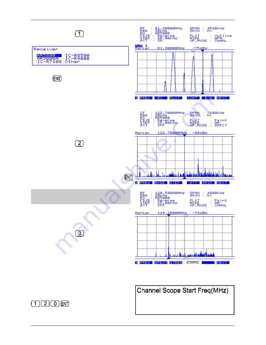
2) Go to menu 1, use the
PREV
NEXT
keys or
press the numeric key
. Push the
RX
key to
access the companion radio configuration menu.
Rotate the spin wheel dial to highlight “AR5000”
then press
. The message “AR5000 Connected”
will be briefly displayed on the SDU5500, if an error
message “RX Disconnected” appears, re-check the
connections and the RS232 parameters of the
AR5000 (the SDU5500 may try two or three times to
connect to the AR5000).
Other items such as
PLOT
,
CONT
,
B/W
can be
ignored unless necessary. The frequency sweep
direction
FDIR
is default and cannot be changed.
3) Go to menu 2, use the
PREV
NEXT
keys or
press the numeric key
. The
MODE
,
ATT
and
STEP
are automatically transferred from the
AR5000 to the SDU5500, however re-check the
attenuator setting. Press
ATT
to toggle the
attenuator status, in this example switch the
attenuator off. Push the
MODE
key to select
receive mode, in this example “AM” followed by
.
&
Note: There is no need to define the channel
step at this point.
The
GAIN
key accesses the SDU5500 gain control,
leave this in the default “Hi” (high) position.
4) Go to menu 3, use the
PREV
NEXT
keys or
press the numeric key
. This menu dictates the
operating mode of the SDU5500:
SPECT = Spectrum display
STRES = Step Resolution
CHANL = Channel scope mode
Push
CHANL
to select channel scope mode, the LCD legend “OP.MODE : CHANL” will later confirm
selection.
5) A new menu will appear “Channel Scope Start
Freq(MHz)” inviting you to enter the lower frequency
limit in MHz format. In this example input 120 MHz
Section 5-4


