background image

After you finish the setting of jumpers and connect correct cables. Power on
and enter the BIOS Setup, press <Del> during POST (Power On Self Test).
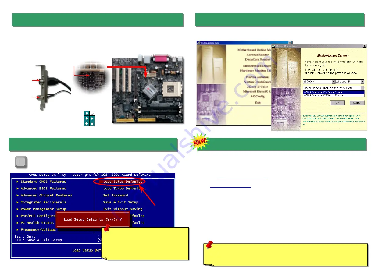
Choose "Load Setup Defaults" for recommended optimal performance.   


15. Power-on and Load BIOS Setup 

16. AOpen Bonus Pack CD 

You can use the autorun menu of Bonus CD disc. Choose the utility and driver and select
model name.   

Del 

Warning:  Please avoid of using "Load 
Turbo Defaults", unless you are sure 
your system components (CPU, 
SDRAM, HDD, etc.) are good enough for 
turbo setting.

1  2 

5  6 

Composite Video

GND

Luma

KEY 
GND 
Chroma 

Pin 1 

TV Output Connector 

S-Terminal 

AV-Terminal 

This motherboard comes with Nvidia nForce2-GT chipsets, which allows you to accept digital
graphic input signal, and encodes, and transmit data through DVI or TV Output. Both NTSC
and PAL TV formats are supported for this function. You may just install a Video Port bracket
(as shown) to your back panel, connecting S-Terminal or AV-terminal to your TV, then using it 
as your another monitor.       

14. TV Output Connector


Warning: The upgrade of new BIOS will permanently replace your original BIOS 
content after flashing. The original BIOS setting and Win2000/WinXP PnP 
information will be refreshed and you probably need to re-configure your system.


17. BIOS Upgrade under Windows Environment 

You may accomplish BIOS upgrade procedure with EzWinFlash by the following steps,
and it’s STRONGLY RECOMMENDED to close all the applications before you start the
upgrading. 
1.  Download the new version of BIOS package zip file from AOpen official web site.

(ex: 

http://english.aopen.com.tw

)   

2.  Unzip the download BIOS package (ex: WMK79GN102.ZIP) with WinZip

(

http://www.winzip.com

) in Windows environment. 

3.  Save the unzipped files into a folder, for example, WMK79GN102.EXE &

WMK79GN102.BIN. 

4.  Double click on the WMK79GN102.EXE, EzWinFlash will detect the model name

and BIOS version of your motherboard. If you had got the wrong BIOS, you will not
be allowed to proceed with the flash steps. 

5.  You may select preferred language in the main menu, then click [Start Flash] to start

the BIOS upgrade procedure. 

6.  EzWinFlash will complete all the process automatically, and a dialogue box will pop

up to ask you to restart Windows. You may click [YES] to reboot Windows. 

7.  Press <Del> at POST to enter BIOS setup, choose "Load Setup Defaults", then

“Save & Exit Setup”. Done! 

Summary of Contents for MK79G-1394

Page 1: ...ector CNR Expansion Slot 32 bit PCI Expansion Slot x3 2 nd USB 2 0 Port Connector Game Port Connector SYSFAN3 Front Audio Connector Front Panel Connector JP14 CMOS Data Clear Jumper STBY LED Chassis Intrusion Sensor Connector S PDIF Connector MK79G 1394 only JP28 USB Keyboard Mouse Wakeup 4Mbit Phoenix Award Flash ROM JP27 USB keyboard Mouse Wakeup IrDA Connector RealTek RTL8201BL PS 2 Mouse Conne...

Page 2: ...nction which could resume your system from suspend mode with keyboard or mouse installed JP28 controls 1 st USB channel and JP27 controls 2 nd USB channel The factory default setting is set to Disable 1 2 and you may enable this function by setting the jumper to 2 3 You can clear CMOS to restore system default setting To clear the CMOS follow the procedure below 1 Turn off the system and unplug th...

Page 3: ...Hz 10 5x AthlonXP 1700 1 46GHz 266MHz 11 0x AthlonXP 1800 1 53GHz 266MHz 11 5x AthlonXP 1900 1 6GHz 266MHz 12 0x AthlonXP 2000 1 667GHz 266MHz 12 5x AthlonXP 2100 1 73GHz 266MHz 13x AthlonXP 2200 1 80GHz 266MHz 13 5x AthlonXP 2400 2 0GHz 266MHz 15x AthlonXP 2600 2 13GHz 266MHz 16x AthlonXP 2700 2 16GHz 333MHz 13x AthlonXP 2800 2 25GHz 333MHz 13 5x Duron 800 800MHz 200MHz 8 0x Duron 850 850MHz 200M...

Page 4: ...ding pins If you enable Suspend Mode item in BIOS Setup the ACPI Power LED will keep flashing while the system is in suspend mode Locate the power switch cable from your ATX housing It is 2 pin female connector from the housing front panel Plug this connector to the soft power switch connector marked SPWR 8 Connecting IDE Floppy Cables Pin 1 ATA 66 100 133 IDE Connector Connect 34 pin floppy cable...

Page 5: ...mally there are two S PDIF outputs as shown one for RCA connector the most common one used for consumer audio products and the other for optical connector with better audio quality Same as outputs you can also connect RCA or optical audio products to input connectors on the module and have the voice or music come out from your computer However you must have a S PDIF supported speaker amplifier dec...

Page 6: ...nently replace your original BIOS content after flashing The original BIOS setting and Win2000 WinXP PnP information will be refreshed and you probably need to re configure your system 17 BIOS Upgrade under Windows Environment You may accomplish BIOS upgrade procedure with EzWinFlash by the following steps and it s STRONGLY RECOMMENDED to close all the applications before you start the upgrading 1...

Page 7: ...ed by power supply or motherboard failure Please contact your reseller or local distributor for repairing Perhaps your VGA card or monitor is defective No Yes No Yes It is very possible that your keyboard is defective During system rebooting press Del to enter BIOS Setup Choose Load Setup Default The problem should be caused by the IDE cables or HDD itself Re install Windows 95 Windows 98 or Windo...

Page 8: ... choose Manuals to go to our manual database You can also find the manual and EIG in AOpen Bonus Pack http club aopen com tw downloads 1 1 Test Report We recommend you to choose board card device from the compatibility test reports for assembling your PC It may prevent incompatibility problems http english aopen com tw tech report default htm 2 2 FAQ Here we list problems that users often encounte...

Reviews: