background image

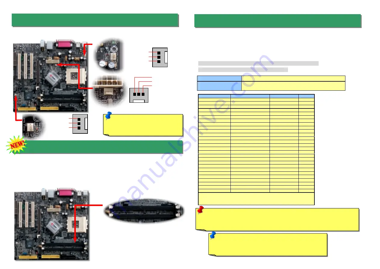
Plug in the CPU fan cable to the 3-pin 

CPUFAN1 

connector. If you have chassis fan, you 

can also plug it on 

SYSFAN2 

or 

SYSFAN3 

connector.


5. Setting CPU Voltage & Frequency 

4. Memory Module (128-Bit DDR Dual Channel) 

3. Installing CPU & Housing Fan 

Note:  Some CPU fans do not have 
sensor pin, so that cannot support 
fan monitoring. 

SYSFAN2 Connector

CPUFAN1 Connector

Full-range Adjustable CPU Core Voltage

This motherboard supports CPU VID function. The CPU core voltage will be automatically 
detected and the range is from 1.1V to 1.85V. It is not necessary to set CPU Core Voltage. 

Setting CPU Frequency 

This motherboard is CPU jumper-less design, you can set CPU frequency through the 
BIOS setup, and no jumpers or switches are needed. 

BIOS Setup > Frequency / Voltage Control > CPU Speed Setup


Core Frequency = CPU FSB Clock * CPU Ratio 
 

CPU Ratio 

From 5.5x to 16x step 0.5x 

CPU FSB (Adjustment 
manually) 

FSB = 100MHz-200MHz by 1MHz Stepping CPU Overclocking 


CPU 

CPU Core Frequency


EV6 Bus Clock


Ratio


Athlon 1G 

1GHz 

200MHz 

10.0x 

Athlon 1.1G 

1.1GHz 

200MHz 

11.0x 

Athlon 1.2G 

1.2GHz 

200MHz 

12.0x 

Athlon 1.3G 

1.3GHz 

200MHz 

13.0x 

Athlon 1G 

1GHz 

266MHz 

7.5x 

Athlon 1.13G 

1.13GHz 

266MHz 

8.5x 

Athlon 1.2G 

1.2GHz 

266MHz 

9.0x 

Athlon 1.33G 

1.33GHz 

266MHz 

10.0x 

Athlon 1.4G 

1.4GHz 

266MHz 

10.5x 

AthlonXP 1500+ 

1.3GHz 

266MHz 

10.0x 

AthlonXP 1600+ 

1.4GHz 

266MHz 

10.5x 

AthlonXP 1700+ 

1.46GHz 

266MHz 

11.0x 

AthlonXP 1800+ 

1.53GHz 

266MHz 

11.5x 

AthlonXP 1900+ 

1.6GHz 

266MHz 

12.0x 

AthlonXP 2000+ 

1.667GHz 

266MHz 

12.5x 

AthlonXP 2100+ 

1.73GHz 

266MHz 

13x 

AthlonXP 2200+ 

1.80GHz 

266MHz 

13.5x 

AthlonXP 2400+ 

2.0GHz 

266MHz 

15x 

AthlonXP 2600+ 

2.13GHz 

266MHz 

16x 

AthlonXP 2700+ 

2.16GHz 

333MHz 

13x 

AthlonXP 2800+ 

2.25GHz 

333MHz 

13.5x 

Duron 800 

800MHz 

200MHz 

8.0x 

Duron 850 

850MHz 

200MHz 

8.5x 

Duron 900 

900MHz 

200MHz 

9.0x 

Duron 950 

950MHz 

200MHz 

9.5x 

Duron 1G 

1GHz 

200MHz 

10.0x 

Duron 1.1G 

1.1GHz 

200MHz 

11.0x 

Note:

 With CPU speed changing rapidly, there might be fastest CPU on the 

market by the time you received this installation guide. This table is kindly for 
your references only. 

Warning: Nvidia nForce2-G/GT supports 166MHz FSB (with performance reaches 
maximum 333MHz EV6 system bus) and 66MHz AGP clock, higher clock setting 
may cause serious system damage.


GND 
+12V 
SENSOR

SYSFAN3 Connector 

SENSOR

+12V

GND

In the past, we used to have 64-bit memory bandwidth for memory access. No matter how 
many memory modules have been installed, though capacity added, the speed of access 
remains the same. With 128-bit dual channel introduced, it doubles the memory bandwidth 
up to 5.4GB in advanced 128-bit mode. This motherboard supports DDR400/333/266 with 
Maximum capacity up to 2GB (When enabling VGA onboard, memory can run max. up to 
333MHz) 

128-bit DDR Dual Channel 

Memory module 

Note: You have to adjust CPU FSB in BIOS after installing 
CPU; otherwise CPU will run at default speed of CPU FSB 
value.


SENSOR

+12V

GND

Summary of Contents for MK79G-1394

Page 1: ...ector CNR Expansion Slot 32 bit PCI Expansion Slot x3 2 nd USB 2 0 Port Connector Game Port Connector SYSFAN3 Front Audio Connector Front Panel Connector JP14 CMOS Data Clear Jumper STBY LED Chassis Intrusion Sensor Connector S PDIF Connector MK79G 1394 only JP28 USB Keyboard Mouse Wakeup 4Mbit Phoenix Award Flash ROM JP27 USB keyboard Mouse Wakeup IrDA Connector RealTek RTL8201BL PS 2 Mouse Conne...

Page 2: ...nction which could resume your system from suspend mode with keyboard or mouse installed JP28 controls 1 st USB channel and JP27 controls 2 nd USB channel The factory default setting is set to Disable 1 2 and you may enable this function by setting the jumper to 2 3 You can clear CMOS to restore system default setting To clear the CMOS follow the procedure below 1 Turn off the system and unplug th...

Page 3: ...Hz 10 5x AthlonXP 1700 1 46GHz 266MHz 11 0x AthlonXP 1800 1 53GHz 266MHz 11 5x AthlonXP 1900 1 6GHz 266MHz 12 0x AthlonXP 2000 1 667GHz 266MHz 12 5x AthlonXP 2100 1 73GHz 266MHz 13x AthlonXP 2200 1 80GHz 266MHz 13 5x AthlonXP 2400 2 0GHz 266MHz 15x AthlonXP 2600 2 13GHz 266MHz 16x AthlonXP 2700 2 16GHz 333MHz 13x AthlonXP 2800 2 25GHz 333MHz 13 5x Duron 800 800MHz 200MHz 8 0x Duron 850 850MHz 200M...

Page 4: ...ding pins If you enable Suspend Mode item in BIOS Setup the ACPI Power LED will keep flashing while the system is in suspend mode Locate the power switch cable from your ATX housing It is 2 pin female connector from the housing front panel Plug this connector to the soft power switch connector marked SPWR 8 Connecting IDE Floppy Cables Pin 1 ATA 66 100 133 IDE Connector Connect 34 pin floppy cable...

Page 5: ...mally there are two S PDIF outputs as shown one for RCA connector the most common one used for consumer audio products and the other for optical connector with better audio quality Same as outputs you can also connect RCA or optical audio products to input connectors on the module and have the voice or music come out from your computer However you must have a S PDIF supported speaker amplifier dec...

Page 6: ...nently replace your original BIOS content after flashing The original BIOS setting and Win2000 WinXP PnP information will be refreshed and you probably need to re configure your system 17 BIOS Upgrade under Windows Environment You may accomplish BIOS upgrade procedure with EzWinFlash by the following steps and it s STRONGLY RECOMMENDED to close all the applications before you start the upgrading 1...

Page 7: ...ed by power supply or motherboard failure Please contact your reseller or local distributor for repairing Perhaps your VGA card or monitor is defective No Yes No Yes It is very possible that your keyboard is defective During system rebooting press Del to enter BIOS Setup Choose Load Setup Default The problem should be caused by the IDE cables or HDD itself Re install Windows 95 Windows 98 or Windo...

Page 8: ... choose Manuals to go to our manual database You can also find the manual and EIG in AOpen Bonus Pack http club aopen com tw downloads 1 1 Test Report We recommend you to choose board card device from the compatibility test reports for assembling your PC It may prevent incompatibility problems http english aopen com tw tech report default htm 2 2 FAQ Here we list problems that users often encounte...

Reviews: