


P/N 1011512 Rev A 10/18
9
System Settings
Follow these steps to access and edit the
system settings.
1.
From the
Heating
or
Ready
screen,
press the
Tools
icon
.
2.
This opens the
Tools
screen shown
below.
3.
To work with settings items, press
the
System Settings
icon
. This
opens the
System Settings
screen
shown below.
4.
From this screen you can change the
following system settings:
y
Degrees
: F/C
y
Beep
(sounds when cooking
cycle completes). Options
are: HI, LO, and OFF.
y
Click
(the sound that accompanies
each screen press). Options
are: HI, LO, and OFF.
y
Heater
(setpoint temperature
of the unit heater in degrees
Fahrenheit): Range is 250° F to
500° F in five degree increments.
y
Reheat
(when the heater
temperature falls below this
setting, the unit displays the
Heating, please wait message.
The unit returns to the ready
screen when the temperature
reaches the Heater temperature
above): Range is 250° F to 500°
F in five degree increments.
y
Shot
(the amount of time the water
valve is open in milliseconds.
This controls how much water is
sprayed onto the heater with each
shot): Range is 0.010 to 2.500
in 10 millisecond increments.
NOTICE:
You must press the radio
button next to each setting
before you can adjust it.
5.
Once you have changed the System
settings as desired, press the
Save
icon
. The system saves the
changes to memory.
To cancel your changes, press the
Cancel
icon to return to the
Tools
screen.
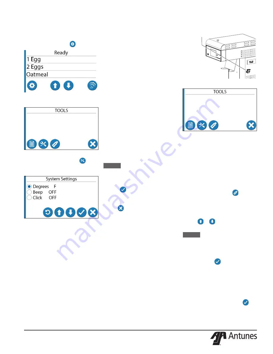
Loading Menu Data via
USB
The steamer is equipped with a USB in-
terface on the side of the unit (see Figure
4). This allows you to load menu items
into the system. To load a menu file:
Make sure the unit displays the
Ready
or
Heating
screen. Insert the USB memory
stick loaded with the electronic menu file
into the USB connector.
Press the
Tools
icon to open the Tools
screen.
Press the
USB Import
icon
. The
system reads the USB device and
displays a list of acceptable menu files on
the
USB Import
screen.
Use the
Up
and
Down
arrow icons on the
display (
or
) to locate the proper
file name.
NOTICE:
The system displays one
file name at a time. Be sure to
scroll through the choices to
find the appropriate file.
When the proper file name appears on
the screen, press
to begin loading the
file into the system.
When the import is complete, the system
displays:
Copy Completed
Remove USB, Press OK
Remove the USB stick and press
.
The system returns to the
Tools
Screen.
You can verify the import by going back
to the
Ready
screen by pressing the
cancel button.
USB connector
Figure 4. USB connector


