background image

Antti-Teollisuus Oy 

408012 

06-2018

SHUTTER PLATE, OPERATED BY LINEAR ACTUATOR

The shutter plate package includes the required fittings for installation in the E-elevators. 

The electric connections shall be made in accordance with the documentation, included in the delivery.

Content of package (

32828

)

Summary of Contents for E-series

Page 1: ...Shutter plate operated by linear actuator Elevators E series 408012 en 06 2018 ANTTI TEOLLISUUS OY Koskentie 89 FIN25340 Kanunki Salo Tel 358 2 774 4700 Fax 358 2 774 4777 E mail antti antti teollisuus fi www antti teollisuus fi ...

Page 2: ......

Page 3: ...ation in the E series elevator 6 Attachment of the frame plate E model 7 Attachment of the draw support 8 Supporting the linear actuatorrod 8 Cutting and attachment of shutter plate rods 9 Connecting the cables to the linear motor 11 LOCATION OF SENSORS 12 GUARANTEE TERMS 14 EU Declaration of Conformity 15 Contents ...

Page 4: ...TE OPERATED BY LINEAR ACTUATOR The shutter plate package includes the required fittings for installation in the E elevators The electric connections shall be made in accordance with the documentation included in the delivery Content of package 32828 ...

Page 5: ...d bracket 1 9 503513 Shutter plate rod 2 10 111565 Shutter plate rod M14 2 11 120545 Compression spring 2 12 110810 Nut Nyloc M12 1 13 101849 Hexagon screw M8x30 19 14 111501 Nut M8 19 15 16 102570 Hexagon screw M12x50 2 17 110570 Nut M12 1 18 19 102240 Hexagon screw M10x100 2 20 110560 Nut M10 6 21 300368 Linear actuator 1 22 119020 Conductor strap 3 6X203 4 23 111511 Washer M8 4 24 25 26 300295 ...

Page 6: ...Antti Teollisuus Oy 6 408012 06 2018 Installation in the E series elevator Fig 1 Installation in elevator E 3pcs at regular distances NOTE THE SHUTTER PLATE EDGE POINTS AWAY FROM THE ELEVATOR PIPES ...

Page 7: ...rame plate part 1 or at the draw support part3 Fix the frame plate at the four points shown in Fig 2 It pays to put the screws for the sup port against buckling part 19 in place before fi xing See Supporting the linear actuator rod on the next page Fig 2 Attachment of the frame plate to the elevator pipe Cover plate of elevator pipe Side plate of elevator pipe Frame plate Fixing points 13 Hexagon ...

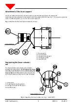
Page 8: ...oo much to avoid bending the linear actuator rod While tightening the nuts parts 20 try the linear actuator rod by hand It must turn easily 1 Frame plate 5 Support against buckling 2pcs 19 Hexagon screw M10x100 2pcs 20 Nut M10 6pcs Attachment of the draw support Choose the attachment point for the draw support so that the distance between its lowermostfi xing screws and the uppermost fi xing screw...

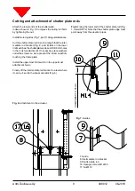
Page 9: ...he shutter plate rod to such a length that the inter mediate rod bracket Fig 8 part 8 falls on the lower limit switch as the shutterplate is closed Drill 8 mm holes in the rods for attachment If necessary place washers underthe screws so as to prevent the screw capsfrom touching the frame plate Install the uppermost limit switch in the uppermost attachment holes Finally lift the intermediate rod b...

Page 10: ...the correct length As the intermediate arm passes the limit swich the limit swich must click and only the roller of the swich hit the intermediate rod bracket The low est limit switch must be correctly positioned in particular in the vertical direction so that in their lowest position the springs will be compressed by a few millimeters but not completely tight ...

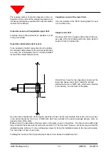
Page 11: ... box to the linear motor Ensure that the seal rings in the connectorsremain in their grooves as the connector ispressed in place After the connection fi x the conductors withstraps part 22 to the linear actuator rod The electric connections shall be made in accordance with the documentation included in the delivery Fig 9 Cables ...

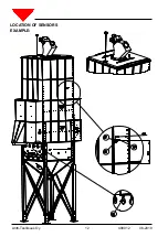
Page 12: ...Antti Teollisuus Oy 12 408012 06 2018 LOCATION OF SENSORS EXAMPLE ...

Page 13: ...ge of the front intake part s side plate Head of sensor comes to hopper side Drill ø30 mm holes for the capacitive sensors at the lower and hopper lower limit Install the sensors putting the two pcs of M30 nuts which were included in the delivery on both sides of the plate Use the sensor bracket 27 for fixing the capacitive sensor as the intermediate limit sensor Fix the sensor in the sensor brack...

Page 14: ... daily allowances which are incurred as a result of replacing any parts The guarantee does not cover the assembly and adjustment of the machinery Restrictions Compensation under the guarantee will not be made in the following cases 1 If the cause of the fault is normal wear abnormal operating conditions incorrect installation inadequate servicing carelessness or unintended use 2 The defect has res...

Page 15: ...5340 KANUNKI Finland Tel 358 2 7744700 Fax 358 27744777 declares that SHUTTER PLATE OPERATED BY LINEAR ACTUATOR conforms with the provisions of the following directives Machine Directive 2006 42 EC Electro Magnetic Compatibility Directive EMC 2004 108 EC Kuusjoki 12 06 2018 Kalle Isotalo Managing Director ...

Reviews: