background image

10

Internal LF and Pulse Generators (Option 27)

An internal pulse generator and two internal waveform generators are added, one provid-
ing a frequency or phase modulating signal and the other an amplitude modulating signal. 
This Internal LF and Pulse Generators option can only be ordered in combination with 
either FM/

Φ

M, AM, or Pulse options, 12, 14, and 26 respectively.

Waveforms:

 Sinusoid, square-wave, triangle, positive ramp, negative ramp, Gaussian 

noise, uniform noise. (Check Option 10 for User-Defined)

Rate:


0.1 Hz to 10 MHz sinusoidal 
0.1 Hz to 1 MHz square-wave, triangle, ramps

Resolution:

 0.1 Hz

Accuracy:

 Same as instrument timebase ±0.014 Hz

Waveform Outputs:

 Two BNC connectors on the rear panel, FM/

Φ

M OUT and AM OUT

Pulse Modes:

 Singlet, doublet, triplet, quadruplet

Pulse Triggers:

 Free-run, triggered, gated, delayed, triggered with delay, swept-delay

Pulse Inputs/Outputs:

 Video pulse and sync out, rear-panel BNC connectors

 For 50 and 67 GHz units, overshoot >40 GHz is 20% typical at rated power.

② 

Period must be longer than the sum of delay and width by 5 clock cycles minimum.

③  

Rise time and Pulse Width Compression, >20 GHz, degrades by 2 ns,  
with High Power Option 15.

*  Typical

Amplitude Modulation (Option 14)

Option 14 adds amplitude modulation, driven externally via a rear panel BNC connector 50 Ω. 

For internal modulation, add Internal LF and Pulse Generators Option 27.

All amplitude modulation specifications apply at 50% depth, 1 kHz rate, with RF level set 
6 dB below maximum specified leveled output power, unless otherwise noted. Amplitude 
Modulation is not available <10 MHz with Option 22.

AM Depth (typical):

 0-90% linear; 20 dB log

AM Bandwidth (3 dB):


DC to 50 kHz minimum 
DC to 100 kHz typical

Flatness (DC to 10 kHz rates):

  ±0.3 dB

Accuracy:

 Reading ±5%

Distortion:

 <5% typical

Incidental Phase Modulation (30% depth, 10 kHz rate):


<0.2 radians typical

External AM Input:

 Log AM or Linear AM input, rear-panel BNC, 50 Ω input impedance. 

For internal modulation, add LF Generator Option 27.

Sensitivity:

Log AM:

 Continuously variable from 0 dB per volt to 25 dB per volt. 

Linear AM:

 Continuously variable from 0% per volt to 100% per volt.

Maximum Input:

 ±1Vpk

Pulse Modulation (Option 26)

Option 26 adds pulse modulation, driven externally via a rear panel BNC connector, TTL. 
For internal modulation, add Internal LF and Pulse Generators Option 27.

Pulse modulation specifications apply at maximum rated power, unless otherwise noted. 
Pulse modulation is not available <10 MHz with Option 22.

On/Off Ratio:

 >80 dB (>70 dB with high power Option 15)

Minimum Leveled Pulse Width:


100 ns, 

1 GHz 

1 µs, <1 GHz

Minimum Unleveled Pulse Width:

 <10 ns

Level Accuracy Relative to CW (100 Hz to 1 MHz PRF):


±0.5 dB, 

1 µs pulse width 

±1.0 dB, <1 µs pulse width

Pulse Delay (typical):

 50 ns in External Mode

PRF Range:


DC to 10 MHz, unleveled  
100 Hz to 5 MHz, leveled

External Input:

 Rear-panel BNC. For internal modulation, add Pulse Generator Option 27

Drive Level:

 TTL compatible input

Input Logic:

 Positive-true or negative-true, selectable from modulation menu.
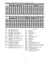
Pulse  

Parameter

Selectable Clock Rate

Narrow (100 MHz)

Wide (10 MHz)

Pulse Width

10 ns to 160 ms

100 ns to 1.6 s

Pulse Period

100 ns to 160 ms

600 ns to 1.6 s

Variable Delay

 Singlet

0 to 160 ms

0 to 1.6 s

 Doublet

100 ns to 160 ms

300 ns to 1.6 s

 Triplet

100 ns to 160 ms

300 ns to 1.6 s

 Quadruplet

100 ns to 160 ms

300 ns to 1.6 s

Resolution

10 ns

100 ns

Accuracy

10 ns (5 ns typical)

10 ns (5 ns typical)

Frequency 

Range

Rise and Fall 

Time 

(10% to 90%)

Overshoot

Pulse Width 

Compression

Video 

Feedthrough

10 to <31.25 MHz  

(Opt. 4)

400 ns*

33%*

40 ns*

±70 mV*

31.25 to <125 MHz  

(Opt. 4)

90 ns*

22%*

12 ns*

±130 mV*

125 to <500 MHz  

(Opt. 4)

33 ns*

11%*

12 ns*

±70 mV*

500 to <2200 MHz  

(Opt. 4)

15 ns*

10%

12 ns*

±50 mV*

10 to <1000 MHz  

(Opt. 5)

15 ns, 10 ns*

10%

8 ns*

±30 mV*

1 to <2 GHz  

(Opt. 5)

10 ns, 5 ns* 

10%

8 ns*

±30 mV* 

2 to 67 GHz

10 ns, 5 ns*

10%

8 ns*

±30 mV*

Summary of Contents for MG3690B

Page 1: ...age leveled output power spectral purity switching speed modulation performance size upgradeability reliability and service Our signal generators are configurable for a broad range of applications from R D to manufacturing and depot repair Anritsu provides you a total solution including proven reliability and standard 3 year warranty plus pre and post sale support that is the best in the industry ...

Page 2: ...nge of the instrument If the step size does not divide into the selected frequency range the last step is truncated Dwell Time Per Step Variable from 1 ms to 99 seconds Fixed Rate Sweep Allows the user to set the total time of the sweep including lock time Variable from 20 ms to 99 seconds Analog Sweep Mode Option 6 Sweep Width Independently selected from 1 MHz to full frequency range With Option ...

Page 3: ...438A and ML4803A and HP 437B 438A and 70100A Five user tables are avail able with up to 801 points table Warm Up Time From Standby 30 minutes From Cold Start 0 deg C 120 hours to achieve specified frequency stability with aging Instruments disconnected from AC line power for more than 72 hours require 30 days to return to specified frequency stability with aging Power 85 264 Vac 48 440 Hz 250 VA m...

Page 4: ...1 Hz to 10 MHz Option 22 30 dBc 10 MHz to 100 MHz Option 4 40 dBc 100 MHz to 2 2 GHz Option 4 50 dBc 10 MHz to 50 MHz Option 5 30 dBc 50 MHz to 2 GHz Option 5 40 dBc 2 GHz 2 2 GHz w Option 4 to 20 GHz 60 dBc 20 GHz to 40 GHz 40 dBc 40 GHz to 50 GHz MG3695B 40 dBc 40 GHz to 67 GHz MG3696B 25 dBc Frequency Range Standard 0 1 Hz to 10 MHz Option 22 30 dBc 10 MHz to 2 2 GHz Option 4 60 dBc 10 MHz to 2...

Page 5: ...6 GHz 54 60 77 86 104 108 108 113 107 112 130 136 6 GHz to 10 GHz 52 57 73 81 100 105 107 114 107 113 128 136 10 GHz to 20 GHz 45 49 68 76 94 100 102 108 102 107 125 135 20 GHz to 40 GHz 45 49 63 70 92 94 98 102 98 101 119 129 40 GHz to 67 GHz 37 40 57 69 86 88 92 96 90 95 113 123 Frequency Range Offset from Carrier 100 Hz 1 kHz 10 kHz 100 kHz 0 1 Hz to 10 MHz Option 22 90 110 120 125 130 139 130 ...

Page 6: ...able MG3693B w opt 4 or 5 STD STD STD 2 GHz 2 to 10 GHz 10 to 20 GHz 20 to 30 GHz 15 0 15 0 12 0 6 0 14 0 14 0 10 0 3 0 Not Available MG3694B w opt 4 or 5 STD STD STD 2 GHz 2 to 10 GHz 10 to 20 GHz 20 to 40 GHz 15 0 15 0 12 0 6 0 14 0 14 0 10 0 3 0 Not Available MG3695B w opt 4 or 5 STD STD 2 GHz 2 to 20 GHz 20 to 50 GHz 12 0 10 0 3 0 10 0 8 0 0 0 Not Available MG3696B w opt 4 or 5 STD STD 2 GHz 2...

Page 7: ...pt 4 or 5 w o opt 4 or 5 2 GHz 2 to 10 GHz 2 to 10 GHz 19 0 23 0 25 0 18 0 21 0 23 0 15 0 16 0 16 0 MG3692B w opt 4 or 5 w opt 4 or 5 w o opt 4 or 5 2 GHz 2 to 20 GHz 2 to 20 GHz 19 0 21 0 23 0 18 0 19 0 21 0 Not Available MG3693B w opt 4 or 5 w opt 4 or 5 w opt 4 or 5 w o opt 4 or 5 w o opt 4 or 5 2 GHz 2 to 20 GHz 20 to 30 GHz 2 to 20 GHz 20 to 30 GHz 17 0 21 0 17 0 23 0 19 0 16 0 19 0 15 0 21 0...

Page 8: ... signal range to an optimum value BNC connector rear panel External Power Meter Levels output power at a remote power meter location Accepts a 1V full scale input signal from the remote power meter L1 adjusts the input signal range to an optimum value BNC connector rear panel External Leveling Bandwidth 30 kHz typical in Detector mode 0 7 Hz typical in Power Meter mode User Level Flatness Correcti...

Page 9: ...8 MHz or 0 03 Fcarrier Unlocked Narrow DC to 10 MHz DC to Lesser of 10 MHz or 0 03 Fcarrier Unlocked Wide DC to 100 Hz DC to 100 Hz Flatness Locked Rate 10 kHz to 1 MHz 1 dB relative to 100 kHz Rate 10 kHz to Lesser of 1 MHz or 0 01 Fcarrier 1 dB relative to 100 kHz Accuracy Locked and Low noise Unlocked Narrow Rate 100 kHz sinewave Int or 1 Vpk Ext 10 5 typical Rate 100 kHz sinewave Int or 1 Vpk ...

Page 10: ...depth 10 kHz rate 0 2 radians typical External AM Input Log AM or Linear AM input rear panel BNC 50 Ω input impedance For internal modulation add LF Generator Option 27 Sensitivity Log AM Continuously variable from 0 dB per volt to 25 dB per volt Linear AM Continuously variable from 0 per volt to 100 per volt Maximum Input 1Vpk Pulse Modulation Option 26 Option 26 adds pulse modulation driven exte...

Page 11: ...dom waveforms one for amplitude modulation and the other for frequency or phase modulation The download files are simple space delimited text files containing inte ger numbers between 0 and 4095 where 0 corresponds to the minimum modulation level and 4095 the maximum In addition to the capability of downloading custom waveforms the software offers a virtual instrument modulation panel Custom modul...

Page 12: ...hich will be used only for purposes of displaying the proper frequency at the output of the mmW module on the MG3690B s front panel display MG3690B with 63850 Series Millimeter Wave Multiplier mmW Frequency Coverage 1 These mmW modules are produced by OML Inc Oleson Microwave Labs co located in Morgan Hill CA with mutual collaborative experiences over many years For detailed and up to date specifi...

Page 13: ... BNC Rear Panel 10 MHz REF OUT BNC Rear Panel HORIZ OUT BNC Rear Panel EFC IN BNC Rear Panel AUX I O 25 pin D type Rear Panel SERIAL I O RJ45 Rear Panel IEEE 488 GPIB Type 57 Rear Panel mmW BIAS Option 18 Twinax Rear Panel RF LO IF Option 7 K Connector female 3x Rear Panel PULSE TRIG IN Option 26 BNC Rear Panel PULSE SYNC OUT Option 27 BNC Rear Panel PULSE VIDEO OUT Option 27 BNC Rear Panel AM IN ...

Page 14: ...de an external lock loop Specifications on page 2 AUX I O Auxiliary Input Output Provides for most of the rear panel BNC connections through a single 25 pin D type connector Supports master slave operation with another synthesizer or allows for a single cable interface with the Model 56100A Scalar Network Analyzer and other Anritsu instruments see figure below SERIAL I O Serial Input Output Provid...

Page 15: ...his option comes in different versions based on instrument configuration MG3690B 16 High Stability Time Base Adds an ovenized 10 MHz crystal oscillator as a high stability time base MG3690B 17 Delete Front Panel Deletes the front panel for use in remote control applications where a front panel display and keyboard control are not needed Only available with Options 1A or 1B MG3690B 18 mmW Bias Outp...

Page 16: ...6 121 SMA male male flexible cable 90 cm 3 ft could be used to con nect the MG3690B output to the module s LO input Accessories 34RKNF50 DC to 20 GHz Ruggedized Type N female adapter for units with a K connector output ND36329 MASTER SLAVE interface cable set 63270 Transit case 16 kg 66 cm x 41 cm x 81 cm roll away on four wheels 2300 469 IVI Driver includes LabView driver 806 97 Aux I O Cable 25 ...

Page 17: ...formance Suite opt 2A 5 28A for MG3692B Opt 38A Ultra Performance Suite opt 2A 3 4 15A 22 28A for MG3692B Opt 39X CW Power Meter and Sensor Bundle Opt 40 Pulse Power Meter and Sensor Bundle Opt 98 Standard calibration to ISO 17025 and ANSI NCSL Z540 Opt 99 Premium calibration to ISO 17025 and ANSI NCSL Z540 Test report and uncertainty data included Footnote 1 Options 4 and 5 MAY NOT be ordered tog...

Page 18: ...18 ...

Page 19: ...19 ...

Page 20: ...one 358 20 741 8100 Fax 358 20 741 8111 Denmark Anritsu A S Kirkebjerg Allé 90 DK 2605 Brøndby Denmark Phone 45 72112200 Fax 45 72112210 Spain Anritsu EMEA Ltd Oficina de Representación en España Edificio Veganova Avda de la Vega no 1 edf 8 pl1 of 8 28108 ALCOBENDAS Madrid Spain Phone 34 914905761 Fax 34 914905762 Russia Anritsu EMEA Ltd Representation Office in Russia Tverskaya str 16 2 bld 1 7th...

Reviews: