


C1
39
60
36
00
_1
.fm
- 19 -
IT
AUS
DE
FR
ES
To carry out this operation, proceed as follows.
1- Turn off the gas supply tap.
2 - Undo the screws (
A
) and remove the control pan-
el (
B
).
3 - Undo the screws (
C
) to remove the support (
D
).
4 - Unscrew the nozzle (
E
) and replace it with the one
suitable for the type of gas in use (see table at
back of manual).
5 - Replace the support (
D
) and the control panel (
B
).
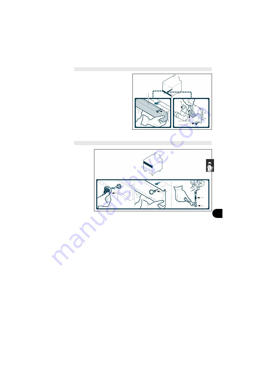
To carry out this operation,
proceed as follows.
1- Turn off the gas supply
tap.
2 - Pull off the knob (
A
).
3 - Undo the screws (
B
) and
remove the control panel
(
C
).
4 - Unscrew the union (
D
).
5 - Extract the nozzle (
E
)
and replace it with the
one suitable for the type
of gas in use (see table at
back of manual).
6 - Retighten the union (
D
).
7 - Replace the control panel (
C
) and the knob (
A
) on
completion of the operation.
REPLACING THE OVEN BURNER NOZZLE
REPLACING THE PLATE BURNER PILOT LIGHT NOZZLE
A
B
IDM-39603618400.tif
D
E
C
A
C
B
E
D
IDM-39603618800.tif