


5
Operation
5.1
Burner Assembly
5.1.1
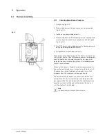
Checking Main Burner Pressure
1. Turn gas supply OFF.
Fig. 10
2. Release bleed screw A and connect pressure gauge tube
(See Fig. 10)
3. Light burner as described previously.
4. Remove cap from port B and adjust pressure using exposed
screw using a 5mm allen key in accordance with data plate
(See Fig. 10).
5. Shut OFF burner as described previously. Remove pressure
gauge tube and tighten bleed screw A.
6. Re-light burner as described previously.
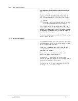
When properly installed and adjusted the Heater will require the
minimum of attention. Should it become necessary to completely
drain the heater, close the cold water inlet valve, open a hot
water tap to allow air to enter the system. Fit a suitable hose to
the drain cock and open.
Whenever the Heater is filled with cold water condensation will
form on the cold storage vessel surfaces when the burner is lit.
Condensation is normal and does not indicate a leak. It will
disappear when the storage vessel becomes heated.
The control thermostat fitted to this heater has a built in limit
thermostat (ECO). In the event of high water temperature the
gas supply will be shut off automatically. The high temperature
condition must be identified and rectified before the heater is
relit. See Section 7 (fault finding).
Note
If in doubt contact Andrews Water Heaters
23
Issue 4 21042018
Summary of Contents for RFF 13/175
Page 8: ...8 Blank Page Issue 4 21042018 ...
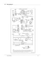
Page 19: ...3 11 Wiring Diagram 19 Issue 4 21042018 ...
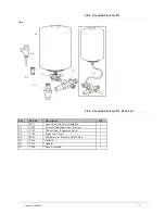
Page 50: ...8 Parts List 8 1 General Assembly 50 Issue 4 21042018 ...
Page 51: ...51 Issue 4 21042018 ...
Page 52: ...52 Issue 4 21042018 ...
Page 53: ...53 Issue 4 21042018 ...
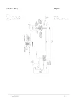
Page 54: ...8 2 Control Box Assembly 54 Issue 4 21042018 ...