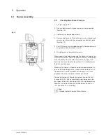


6.3
Gas Control Valve
This should be checked and serviced by an engineer fully
conversant with every aspect of this piece of equipment.
Fig. 25
To remove gas control, unscrew four retaining screws at top and bottom
of gas control bracket. Also it will be necessary to remove gas fittings at
the top of the gas valve and the bottom of the gas valve. It is now
possible to slide the gas control valve away from the gas valve retaining
bracket.
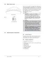
To change the gas valve it is not necessary to drain down the
water heater.
1. Isolate from the electrical supply. Unhook and remove the
outer door and remove the inner door by sliding to the side
2. Disconnect burner gas tube, pilot tube and blue ignition lead
at gas control.
3. Remove burner assembly complete with pipes and blue
ignition lead.
4. Disconnect electrical connection from the top of the heater.
Remove the screws that hold the flue-fan in place and
remove the flue fan.
5. Withdraw the flue baffle.
6. Clean the flueway with a brush and clean any deposit from
the underside of the storage vessel bottom and from the flue
baffle.
7. Re-assemble in the reverse order.
Note
It is important that the burner is correctly located in the
burner support bracket on base of combustion chamber.
8. Re-light and carry out commissioning check.
See
See section 4 commissioning.
33
Issue 4 21042018
Summary of Contents for RFF 13/175
Page 8: ...8 Blank Page Issue 4 21042018 ...
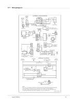
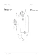
Page 19: ...3 11 Wiring Diagram 19 Issue 4 21042018 ...
Page 50: ...8 Parts List 8 1 General Assembly 50 Issue 4 21042018 ...
Page 51: ...51 Issue 4 21042018 ...
Page 52: ...52 Issue 4 21042018 ...
Page 53: ...53 Issue 4 21042018 ...
Page 54: ...8 2 Control Box Assembly 54 Issue 4 21042018 ...