12)
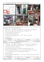
CARD DISPENSER MOTOR ERROR [E.c1],CARD DISPENSER SENSOR ERROR [E.c1]
▶SOLUTION
: CARD DISPENSER MOTOR ERROR [E.c1]
1 HOW TO TEST TEST MODE → CARD DISPEN TEST → SELECT button →SHOOTING button
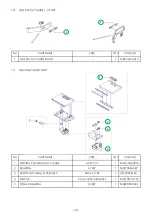
2 Check MOTOR connector connection status ( P1 )
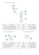
3 Check assembly status ( P2 )
4 Check operation status ( P 2 )
5 voltage check ( CARD DISPENSER PCB / CN7 )
: PIN 5 : 11V 이상 , PIN 2 : GND
6 voltage check ( CARD DISPENSER PCB / CN1 )
: PIN 1 : GND , PIN 3 : 11V 이상
7 MOTOR replacement
8 voltage check ( MAIN PCB / CN21 )
: PIN 1/2 : 11V or higher, PIN 5/6 : GND
9 MAIN PCB replacement
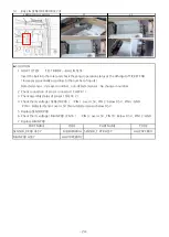
▶SOLUTION
: CARD DISPENSER SENSOR ERROR [E.c1]
1 HOW TO TEST TEST MODE → CARD DISPEN TEST → SELECT button →SHOOTING button
When detected: " _ " / When not detected: " 0 "
2 SENSOR PCB wiring connection and connector connection status check ( P1 )
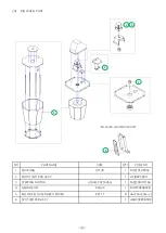
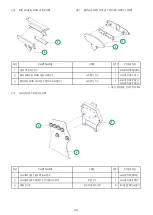
3 Check the sensor assembly status and check the sensor bracket hole and sensor position( P3,P4)
4 voltage check ( SENSOR PCB )
: PIN 3: 4.5V or more, PIN 4: less than 0.5V, PIN 2: GND ,
PIN 1: 4.5V or more when detected / less than 0.5V when not detected
5 SENSOR REPLACEMENT
6 voltage check(CARD DISPENSER PCB/CN5 ): PIN 1: more than 4.5V, PIN 2: less than 0.5V, PIN 3: GND
7 CARD DISPENSER PCB replacement
8 voltage check ( MAIN PCB / CN21 ) : PIN 1/2 : 11V or higher, PIN 5/6 : GND
9 MAIN PCB replacement
PART NAME
CODE
PART NAME
CODE
MOTOR
MZZZ0MOT089 MAIN PCB ASS'Y
AAV10PCB001
PART NAME
CODE
PART NAME
CODE
PHOTO INT-1 PCB ASS'Y
AZZZ0PCB103 MAIN PCB ASS'Y
AAV10PCB001
ERROR OR LOCATION
P1
P2
P3
P4
- 28 -


