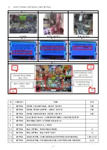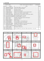
6)
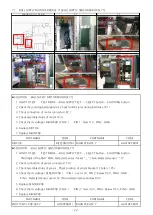
REAR HOPPER MOTOR ERROR [E.62]
▶SOLUTION
: REAR HOPPER MOTOR ERROR [E.62]
1 HOW TO TEST
TEST MODE → REAR HOPPER TEST→ SELECT button→SHOOTING button
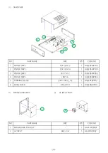
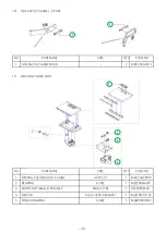
2 Check the jamming location Token Bridge, Pusher Plate and Conveyor ( P1 )
3 Foreign objects inside the HOPPER,Check jamming hopper disk,Check jamming hopper rail ( P 2 )
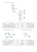
4 Check the disk rotation direction, Check connection of motor connector ( P )
5 Check the operation of HOPPER PCB internal LED1 (lights up during operation),
LED2 (flashes when 5V input), LED3 (flashes when 24V is input) (P4 )
5 Check the dc voltage ( HOPPER PCB / JP2 )
: PIN 1 : Over 23V , PIN 2 : GND
6 Replace HOPPER PCB
7 Check the dc voltage ( MAIN PCB / CN10 ) : B-PIN 1 : Over 23V , B-PIN 6 : Over 4.5V , B-PIN 10 : GND
8 Replace MAIN PCB
▶SOLUTION
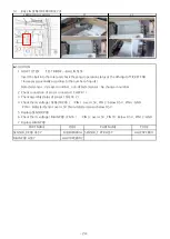
: REAR HOPPER SENSOR ERROR [E.62]
1 HOW TO TEST
TEST MODE → REAR HOPPER TEST→ SELECT button→SHOOTING button
PLAY FND 3rd digit confirms quantity change ( reduced sequentially when sensor is detected )
2 Check the jamming location Token Bridge, Pusher Plate and Conveyor ( P1 )
3 Check the jamming launch part exit ( P 2 )
Check the jamming hopper rail ( P 2 )
4 Check connection of sensor connector ( P5 )
5 Check the foreign substances in the sensor part and the assembly status of the launch part (P4 )
6 Check the dc voltage ( SENSOR ASS'Y ) : PIN 1 : over 4.5V , PIN 3 : below 0.5V , PIN 4 : GND ,
PIN 2 : Detected Sensor over 4.5V / Non-detected sensor below 0.5V
7 Replace SENSOR PCB
8 Replace MAIN PCB
PART NAME
CODE
PART NAME
CODE
MAIN PCB ASS'Y
AAV10PCB001
PART NAME
CODE
PART NAME
CODE
MAIN PCB ASS'Y
AAV10PCB001
ELEVATOR HOPPER PCB ASS'Y
AZZZ0PCB143
ELEVATOR SENSOR ASS'Y
AZZZ0PCB173
P3
P4
P5
ERROR OR LOCATION
P1
P2
- 21 -

