INSTALLATION &
OPERATION MANUAL
8128 River Way, Delta B.C. V4G 1K5 Canada T. 604.946.9981 F. 604.946.9983 TF. 800.668.3884 (US/CANADA)
www.analyticsystems.com
An ISO9001 Registered Company
Battery Chargers
•
Inverters
•
Power Supplies
•
Voltage Converters
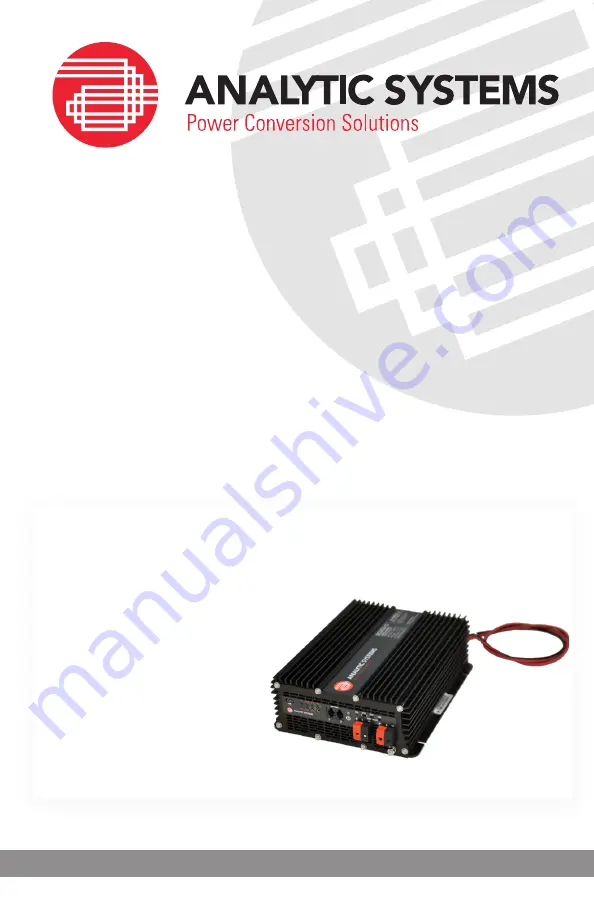
BCDi320
Intelligent DC
Battery Charger


