


4
DEMO MANUAL DC2529A
UG-1311 Rev 0
For more information
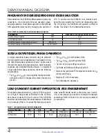
LOW QUIESCENT CURRENT APPLICATIONS AND MEASUREMENT
The typical quiescent current (I
Q
) of the LTC7810 control-
ler is 16µA in sleep mode as specified in the LTC7810
data sheet. However, the input current of the DC2529A
board can be higher than this value because of additional
circuit outside of the IC. To reduce the total input current,
large value FB divider resistors should be used. In addi-
tion, some jumpers and resistors should be configured
accordingly. Refer to Table 3 for the low input quiescent
current setup.
Table 3. Low Input Quiescent Current Configuration
Reference Designator
R39
R40
JP5
JP4
JP6
JP1
Function
OVLO
OVLO
INTV
CC
Jumper
MODE Selector
NDRV Regulator
Spread Spectrum
Stuffing Option
OPEN
As-is
OPEN
BURST ADJ. or
BURST DEFAULT
Short
OFF
FREQUENCY SYNCHRONIZATION AND MODE SELECTION
Demonstration circuit 2529A’s Mode selector allows the
converter to run in forced continuous operation, pulse-
skipping operation, Burst Mode operation or Burst Mode
with adjustable clamp level by changing the position of
Table 2. Mode Selection and Synchronized Operation Options
CONFIGURATION
JP4
MODE WITH SYNC. SIGNAL APPLIED TO PLLIN
Forced Continuous Operation
FCM
FCM
Pulse-Skipping Operation
P.S.
P.S.
Burst Mode Operation with Adjustable Clamp Level
BURST ADJ.
FCM
Burst Mode Operation with Default Clamp
BURST DEFAULT
FCM
JP4. To synchronize the DC2529A to an external clock,
apply the sync signal to the PLLIN turret. Depending upon
the JP4 setting, the DC2529A will operate in different
modes. See Table 2 for the detailed description.
SINGLE OUTPUT/DUAL PHASE OPERATION
A single output/dual phase converter may be preferred
for high output current applications. The benefits of sin-
gle output/dual phase operation is lower ripple current
through the input and output capacitors, faster load step
response and simplified thermal design. To implement
single output/dual phase operation, make the following
modifications:
• Tie V
OUT1
to V
OUT2
by tying together the exposed cop-
per pads on the V
OUT
shapes with pieces of heavy cop-
per foil.
• Tie I
TH1
to I
TH2
by stuffing 0Ω at R43.
• Tie V
FB1
to V
FB2
by stuffing 0Ω at R45.
• Tie SS1 to SS2 by stuffing 0Ω at R44.
• Tie RUN1 to RUN2 by stuffing 0Ω at R42.
• Remove the redundant ITH compensation network, V
FB
divider and SS cap.
• Replace C1, C16 if necessary.
• Re-compensate if necessary.


