


2
DEMO MANUAL DC2529A
UG-1311 Rev 0
For more information
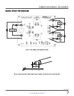
QUICK START PROCEDURE
Demonstration circuit DC2529A is easy to set up to
evaluate the performance of the LTC7810ELXE. Refer to
Figure 1 for proper measurement equipment setup and
follow the procedure below:
NOTE: When measuring the input or output voltage ripple,
care must be taken to avoid a long ground lead on the
oscilloscope probe. Measure the input or output voltage
ripple by touching the probe tip directly across the V
IN
or V
OUT
and GND terminals or directly across relevant
capacitor. See Figure 2 for proper scope probe technique.
1. Place jumpers in the following positions:
JP1 OFF
JP2 ON
JP3 ON
JP4 FCM
JP5 ON
JP6 ON
2. With power off, connect the input power supply to V
IN
and GND.
3. Turn on the power at the input.
NOTE: Make sure that the input voltage is higher than
16V and does not exceed 130V.
4. Check the output voltages. The output voltages should
be within the specifications in Table 1.
Once the proper output voltages are established, adjust
the load within the operating range and observe the
output voltage regulation, output voltage ripple, effi-
ciency and other parameters.
Note 1:
If there is no output, temporarily disconnect the
load to make sure that the load is not set too high.
Note 2:
Do not apply load between the V
OUT1
+
and V
OUT1
–
pins or between the V
OUT2
+
and V
OUT2
–
pins. These pins
are only intended to Kelvin sense the output voltage across
the C27 and C24. Heavy load currents applied across the
V
OUT1
+
, V
OUT1
–
, V
OUT2
+
and V
OUT2
–
sense pins will dam-
age these sense traces.


