3
DEMO MANUAL DC2529A
UG-1311 Rev 0
For more information
www.analog.com
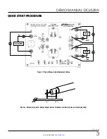
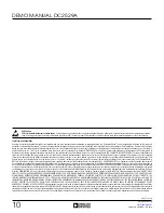
Figure 1. Proper Measurement Equipment Setup
QUICK START PROCEDURE
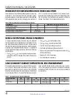
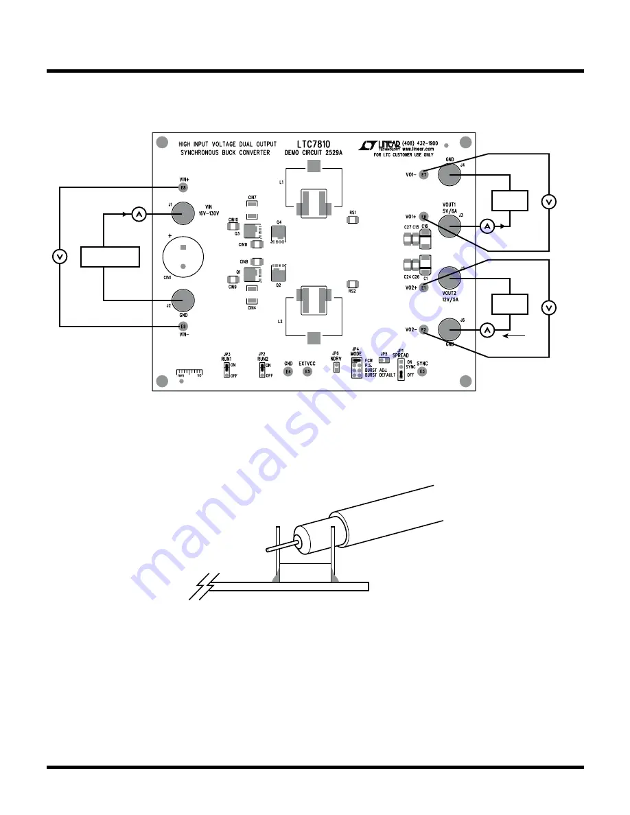
Figure 2. Measuring Input or Output Ripple Across Terminals or Directly Across Ceramic Capacitor
+
–
V
OUT
GND
C
OUT
V
IN
SUPPLY
I
IN
+
–
LOAD
–
+
I
OUT
–
+
LOAD
DC2529A F01
+
–
I
OUT
+
–
+
–