UG-1135
Rev. 0 | Page 14 of 45
8.
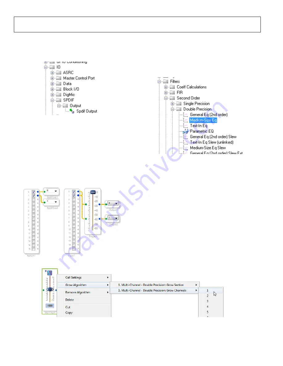
Add two S/PDIF outputs to the project as follows:
a.
From the
IO
>
SPDIF
>
Output
folder, click
Spdif
Output
(see Figure 47) and drag it into the project
space to the right of the toolbox.
15789-
049
Figure 47. S/PDIF Output Block Selection
b.
Repeat the previous step to add another
Spdif
Output
block.
9.
Connect the signals from the
Asrc Input
block to the
Spdif
Output
blocks so that the resulting signal flow resembles
10.
Click the
Link/Compile/Download
button (see Figure 28) or
press F7. The signal flow then compiles and downloads to
the hardware.
11.
Confirm proper operation by checking that any signal
input to the S/PDIF optical receiver is copied and output
on the S/PDIF optical transmitter.
15789-
050
Figure 48. Signal Flow Including S/PDIF Input (via the ASRC) and
S/PDIF Output
Add a Filter
To add a filter, take the following steps:
1.
Add a
Medium-Size Eq
block to the project space as follows:
a.
From the
Filters
>
Second Order
>
Double Precision
folder, click
Medium-Size Eq
(see Figure 49) and drag
it into the project space to the right of the toolbox.
157
89-
051
Figure 49.
Medium-Size Eq
Block Selection
By default, the block has one input and one output (single-
channel). To add another channel, right click in the empty white
space of the
Medium-Size Eq
block, then select
Grow Algorithm
>
1. Multi-Channel – Double Precision: Grow Channels
>
1
from the dropdown menu that appears (see Figure 50).
15
789-
05
3
Figure 50. Adding a Channel to the Filter


