background image

UG-851 

EVAL-AD7605-4SDZ/EVAL-AD7606SDZ/EVAL-AD7607SDZ/EVAL-AD7608SDZ User Guide 


Rev. A | Page 6 of 15 

EVALUATION BOARD SOFTWARE 

SOFTWARE INSTALLATION 

The 

EVAL-AD7605-4SDZ

/

EVAL-AD7606SDZ

/

EVAL-AD7606-

6SDZ

/

EVAL-AD7606-4SDZ

/

EVAL-AD7607SDZ

/

EVAL-

AD7608SDZ

 kit includes the evaluation software on a CD; 

the software is also available for download from the 

AD7606

/

AD7606-6

/

AD7606-4

AD7607

AD7608

, and 

AD7605-4

 product pages. 

There are two parts to the installation: 


AD7606

 evaluation software installation 


EVAL-SDP-CB1Z

 SDP board drivers installation 

Warning 

The evaluation board software and drivers must be installed before 
connecting the 

EVAL-AD7605-4SDZ

/

EVAL-AD7606SDZ

/

EVAL-

AD7606-6SDZ

/

EVAL-AD7606-4SDZ

/

EVAL-AD7607SDZ

/

EVAL-

AD7608SDZ

 evaluation board and SDP board to the USB port 

of the PC to ensure the evaluation system is correctly recognized 

when it is connected to the PC. 

Installing the Evaluation Software 

To install the 

AD7606

 evaluation board software, 

1.


Insert the included evaluation software installation CD 
into the CD drive of a Windows-based PC, and open the 
contents of the CD. 

2.


Double-click the setup.exe file to begin the installation.  
By default, the software is saved to the following location: 
C:\Program Files\Analog Devices\AD7606\

3.


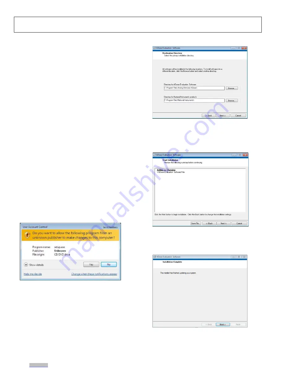
A dialog box appears asking for permission to allow the 
program to make changes to the PC. Click Yes to begin the 
installation process (see Figure 2). 


Figure 2. 

User Account Control

 Dialog Box 

4.


Select a location to install the software, and then click Next 
(see Figure 3). 


Figure 3. Destination Directory Window 

5.


A license agreement appears. Read the agreement, select 
I accept the License Agreement, and click Next

6.


A summary of the installation appears. Click Next to 
continue (see Figure 4). 


Figure 4. Start Installation Window 

7.


A dialog box informs the user when the evaluation 
software installation is complete. Click Next to proceed 
with the installation of the SDP drivers (see Figure 5).  


Figure 5. Installation Complete Window 

8.


The installation of the evaluation software completes.  

13283-

003

13283-

004

13283-

005

13283-

006

Downloaded from

Arrow.com.

Downloaded from

Arrow.com.

Downloaded from

Arrow.com.

Downloaded from

Arrow.com.

Downloaded from

Arrow.com.

Downloaded from

Arrow.com.

Summary of Contents for EVAL-AD7605-4SDZ

Page 1: ...605 4 data sheets EVAL AD7605 4SDZ EVAL AD7606SDZ EVAL AD7606 6SDZ EVAL AD7606 4SDZ EVAL AD7607SDZ EVAL AD7608SDZ user guide Required Software AD7606 evaluation software Design and Integration Files Schematics layout files bill of materials EVALUATION BOARD DESCRIPTION The EVAL AD7605 4SDZ EVAL AD7606SDZ EVAL AD7606 6SDZ EVAL AD7606 4SDZ EVAL AD7607SDZ EVAL AD7608SDZ is a full featured evaluation ...

Page 2: ... Power Supplies Section Channel Input Section EVAL AD7606SDZ Section EVAL AD7607SDZ Section EVAL AD7608SDZ Section EVAL AD7606 6SDZ Section and Table 2 4 Changes to EVAL AD7606 4SDZ Section and Table 3 5 Changes to Installing the Evaluation Software Section Figure 2 Caption Figure 3 Caption Figure 4 Caption and Figure 5 Caption 6 Changes to Installing the SDP Board Drivers Section Figure 6 Caption...

Page 3: ...VAL SDP CB1Z SDP board to the evaluation board as shown in Figure 1 Screw the EVAL SDP CB1Z SDP board and EVAL AD7605 4SDZ EVAL AD7606SDZ EVAL AD7606 6SDZ EVAL AD7606 4SDZ EVAL AD7607SDZ EVAL AD7608SDZ evaluation board together using the enclosed nylon screw nut kit to ensure the boards connect firmly together 4 Connect a 5 V power supply to the J1 connector and ensure Link LK1 is in Position A 5 ...

Page 4: ...VAL AD7606SDZ EVAL AD7606 6SDZ EVAL AD7606 4SDZ EVAL AD7607SDZ EVAL AD7608SDZ evaluation board is used without the 9 V adapter an external power supply in the range 7 V to 9 V must be connected to the J3 terminal block to supply the ADP7104 5 V linear regulator Each supply is decoupled on the EVAL AD7605 4SDZ EVAL AD7606SDZ EVAL AD7606 6SDZ EVAL AD7606 4SDZ EVAL AD7607SDZ EVAL AD7608SDZevaluation ...

Page 5: ...ard The EVAL SDP CB1Z is powered from the ADP7104 5 V linear regulator LK3 B LK3 is used to select theVDRIVE source for the AD7606 AD7606 6 AD7606 4 AD7607 AD7608 and AD7605 4 In Position A the AD7606 AD7606 6 AD7606 4 AD7607 AD7608 and AD7605 4 are supplied with 3 3VVDRIVE In Position B the AD7606 AD7606 6 AD7606 4 AD7607 AD7608 and AD7605 4 are supplied with 5VVDRIVE 5 V VDRIVE runs the device a...

Page 6: ...n CD into the CD drive of a Windows based PC and open the contents of the CD 2 Double click the setup exe file to begin the installation By default the software is saved to the following location C Program Files Analog Devices AD7606 3 A dialog box appears asking for permission to allow the program to make changes to the PC Click Yes to begin the installation process see Figure 2 Figure 2 User Acc...

Page 7: ...ation Window After the evaluation software installation is complete connect the EVAL AD7605 4SDZ EVAL AD7606SDZ EVAL AD7606 6SDZ EVAL AD7606 4SDZ EVAL AD7607SDZ EVAL AD7608SDZ evaluation board to the EVAL SDP CB1Z SDP board as described in the Evaluation Board Hardware section When first plugging in the EVAL SDP CB1Z SDP board via the USB cable provided allow the Found Hardware Wizard to run After...

Page 8: ...ling rates up to 300 kSPS Enter the required sampling rate in the Sampling Rate field see Figure 11 Oversampling The Oversample Mode drop down menu Label 4 in Figure 11 enables and disables oversampling and chooses from rates of oversample by 2 4 8 16 32 and 64 See the AD7606 AD7606 6 AD7606 4 AD7607 AD7608 and AD7605 4 data sheets for more information about the digital filter profile The maximum ...

Page 9: ...gram FFT or Summary tab updates If the Continuous button is clicked the label on the button changes to Stop and the software repeats the capture of the selected number of samples indefinitely until the user clicks Stop While the software is in the continuous capture mode the data in the Waveform Histogram FFT or Summary tab is also continuously updated No data appears on the screen if no active ch...

Page 10: ...re shown The waveform graph displays the information for all eight input channels or as many channels as desired Eight buttons located to the right of the graph labeled ADC 1 ON ADC 1 OFF to ADC 8 ON ADC 8 OFF selects which channel data displays Label 1 in Figure 13 An indicator located to the right of the graph Label 3 in Figure 13 shows what color graph represents each channel when the data from...

Page 11: ...he Histogram tab displays a histogram of the captured ADC codes It can give an indication of the performance of the ADC in response to dc inputs The Histogram Analysis section contains information about the samples taken for example the maximum and minimum codes captured Figure 14 Histogram Tab 13283 015 Downloaded from Arrow com Downloaded from Arrow com Downloaded from Arrow com Downloaded from ...

Page 12: ...out the analysis such as the calculated values of signal to noise ratio SNR signal to noise and distortion SINAD and total harmonic distortion THD see Figure 15 The user can choose to display the information for one several or all eight channels in the FFT tab using the ADC 1 ON ADC 1 OFF to ADC 8 ON ADC 8 OFF buttons Figure 15 FFT Tab 13283 016 Downloaded from Arrow com Downloaded from Arrow com ...

Page 13: ... as well as some of the key performance parameters such as SNR THD S N D and Dynamic Range see Label 1 in Figure 16 Figure 16 Summary Tab 1 13283 017 Downloaded from Arrow com Downloaded from Arrow com Downloaded from Arrow com Downloaded from Arrow com Downloaded from Arrow com Downloaded from Arrow com Downloaded from Arrow com Downloaded from Arrow com Downloaded from Arrow com Downloaded from ...

Page 14: ...ot contain any raw data information Plots saved as images cannot be loaded back into the evaluation environment OPENING FILES Loading Captured Data The software can load previously captured data for analysis Go to the File menu click Load Data and select waveform data previously saved in TSV format The waveform data is a raw data capture that rebuilds the histogram and ac spectrum analyses when lo...

Page 15: ...AL RESTRICTIONS Customer may not disassemble decompile or reverse engineer chips on the Evaluation Board Customer shall inform ADI of any occurred damages or any modifications or alterations it makes to the Evaluation Board including but not limited to soldering or any other activity that affects the material content of the Evaluation Board Modifications to the Evaluation Board must comply with ap...

Reviews: