


EVAL-AD5934EB
Preliminary Technical Data
Rev. PrC | Page 24 of 32
Q:
I have scaled the system clock connected to the AD5934 to
allow an analysis of lower clock frequencies. Although I
established the lower frequency limit, my upper excitation
frequency is now limited. What is the reason for this limitation?
A:
In measuring lower clock frequencies, the two main
tradeoffs are that the AD5934 takes longer to return the
impedance results due to the slower ADC conversion clock
speed and that the upper excitation limit is restricted.
For example, if the user has established that a scaled clock
frequency of 4 MHz must be applied to the external clock pin of
the AD5934 to correctly analyze a 10 kHz signal, the applied
system clock is divided by a factor of 16 before being routed as
the reference clock to the DDS. The system clock is also divided
by a factor of 4 before being connected to the ADC.The ADC
sampling clock is running at four times the speed of the DDS
core. Therefore, with a system clock of 4 MHz, the DDS
reference clock is 1/16 × 4 MHz = 62.5 kHz, and the ADC clock
is 1 MHz. The AD5934 DDS has a 27-bit phase accumulator;
however, the top three most significant bits (MSBs) are
internally connected to Logic 0. Therefore, with the top three
MSBs set to 0, the maximum DDS output frequency is further
reduced by a factor of 1/8, and the maximum output frequency
is 1/128 × 1 MHz = 7.8125 kHz.
Therefore, it is possible to accurately measure the 3 kHz signal
using a lower system clock of 4 MHz; however, the AD5934
takes longer to return the impedance results due to the slower
ADC conversion clock speed and the upper excitation limit is
now restricted to 7.8125 kHz.
Measuring Higher Excitation Frequencies
The AD5934 is specified to a typical system accuracy of 0.5%
within the frequency range of ≈1 kHz up to 100 kHz (assuming
the AD5934 system is calibrated correctly for the impedance
range being tested).
The lower frequency limit is determined by the value of the
system clock frequency connected to the external clock pin
(MCLK) of the AD5934. The lower limit can be reduced by
scaling the system clock (see Measuring Lower Excitation
Frequencies).
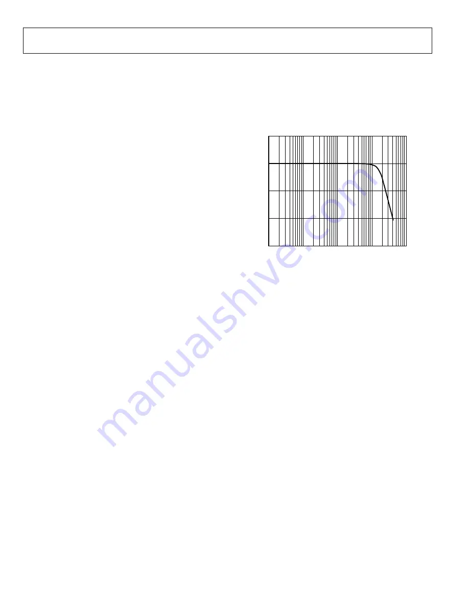
The upper frequency limit of the system is due to the finite
bandwidth of the internal amplifiers coupled with the effects of the
low-pass filter pole locations (for example, 200 kHz and 300 kHz),
which are used to roll off any noise signals from corrupting the
DFT output on the receive side of the AD5934. Therefore, the
AD5934 has a finite frequency response similar to that shown
in Figure 33.
0
–20
–40
–60
100
1k
10k
100k
1M
SYSTEM BANDWIDTH (Hz)
SYST
EM
G
A
IN
(d
B
)
20
05
449
-0
33
Figure 33. Typical AD5934 System Bandwidth
Using the AD5934 to analyze frequencies above 100 kHz
introduces errors in the impedance profile. This is due to the
effect of the increased roll-off in the finite frequency response
of the system for frequencies above 100 kHz. However, if the
user is performing a sweep with a frequency above 100 kHz, it
is important to ensure that the sweep range is as small as
possible, for example, 120 kHz to 122 kHz. The impedance
error from the calibration frequency is approximately linear
over a small frequency range. The user can remove any linear
errors introduced by performing an end-point or multipoint
calibration (see the
data sheet for further details on
end-point calibration).