Evaluation Board User Guide
UG-177
Rev. 0 | Page 7 of 27
CREATING A BASIC SIGNAL FLOW
To access the
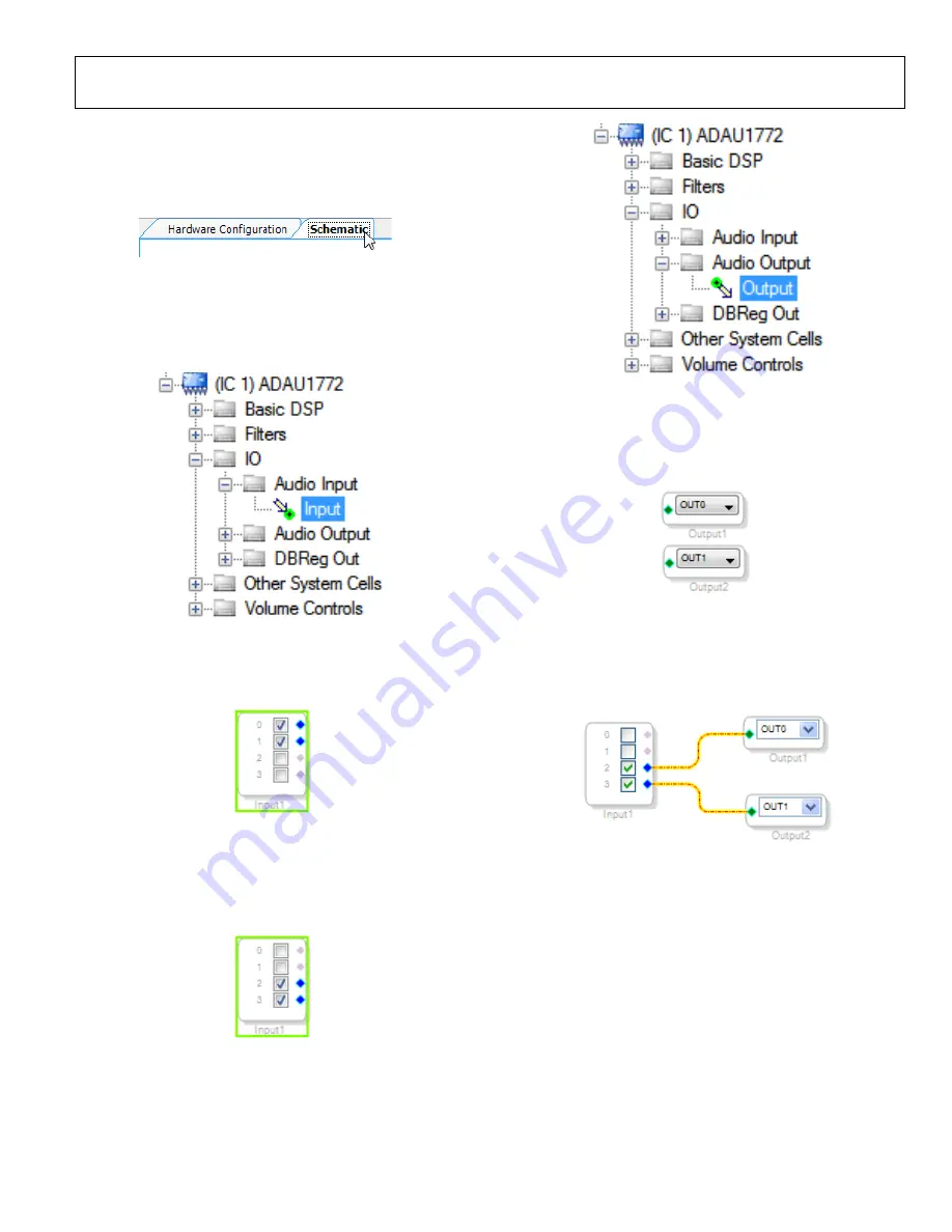
Schematic
tab, where a signal processing flow
can be created, click the
Schematic
tab at the top of the screen
(see Figure 16).
0
83
14
-0
21
Figure 16. Schematic Tab
The left side of the schematic view includes the
Toolbox
, which
contains all of the algorithms that can run in the SigmaDSP.
Select the
Input
cell from within the
IO > Audio Input
folder
(see Figure 17).
Figure 17. Input Cell Selection
Click and drag the
Input
cell into the blank schematic space to
the right of the
Toolbox
(see Figure 18).
Figure 18. Input Cell
Because we are using inputs “
2
” and “
3
” as a stereo pair, deselect
inputs “
0
” and “
1
’” and select input boxes “
2
” and “
3
” (see
Figure 19).
Figure 19. Inputs 2 and 3 selected
Navigate to the
IO >Audio Output
folder and select the
Output
cell (see Figure 20).
Figure 20. Output Cell Selection
Click and drag an output cell to the schematic. Do this again to
create two outputs (see Figure 21). Make sure the output cells
are assigned to “
OUT0
” and “
OUT1
” respectively.
Figure 21. Output Cells
Connect the cells together by left-clicking a blue output dot and
dragging to the green output dot of the next cell, connecting
input “
2
” to “
OUT0
” and input “
3
” to “
OUT1
”(see Figure 22).
Figure 22. Connected Signal Flow
The basic signal flow is now complete with stereo I/O.
To add Volume control via the buttons labeled “VOL-“ and
“VOL+”, add jumpers to S5 and S6 on J9 (See Figure 23).


