


August 2012
L010440
21
ASCII Symbol
Hex Value
ASCII
Symbol
Hex Value
Carriage Return
0D
C
43
0
30
G
47
1
31
H
48
2
32
M
4D
3
33
N
4E
4
34
R
52
5
35
S
53
6
36
V
56
7
37
!
21
8
38
$
24
9
39
+
2B
A
41
-
2D
B
42
_
5F
ASCII Table for Direct Mode
Error Code
Type
Description
1
Receive Overflow
Error
The serial communications had a receiving error. This is an
internal error caused by the computer.
2
Range Error
There was an invalid number of characters sent to the pulse
generator. Check to see if the parameters are invalid for the
command that was sent.
4
Command Error
A bad command was sent to the pulse generator. Please check
to see that the command being sent is valid, or that the pulse
generator is not running.
8
Transmit Error
To many parameters sent back to the PC. This is an internal
error cause by the EEProm.
16
Motor Error
Motor speed profiles are set incorrectly. Please make sure that
the base speed is less than the max speed and that the speeds
are within their valid ranges.
32
Zero Parameters
Error
There were no parameters sent to the pulse generator. A com
-
mand was sent to the pulse generator that expected to see
parameters after the command.
Error Codes
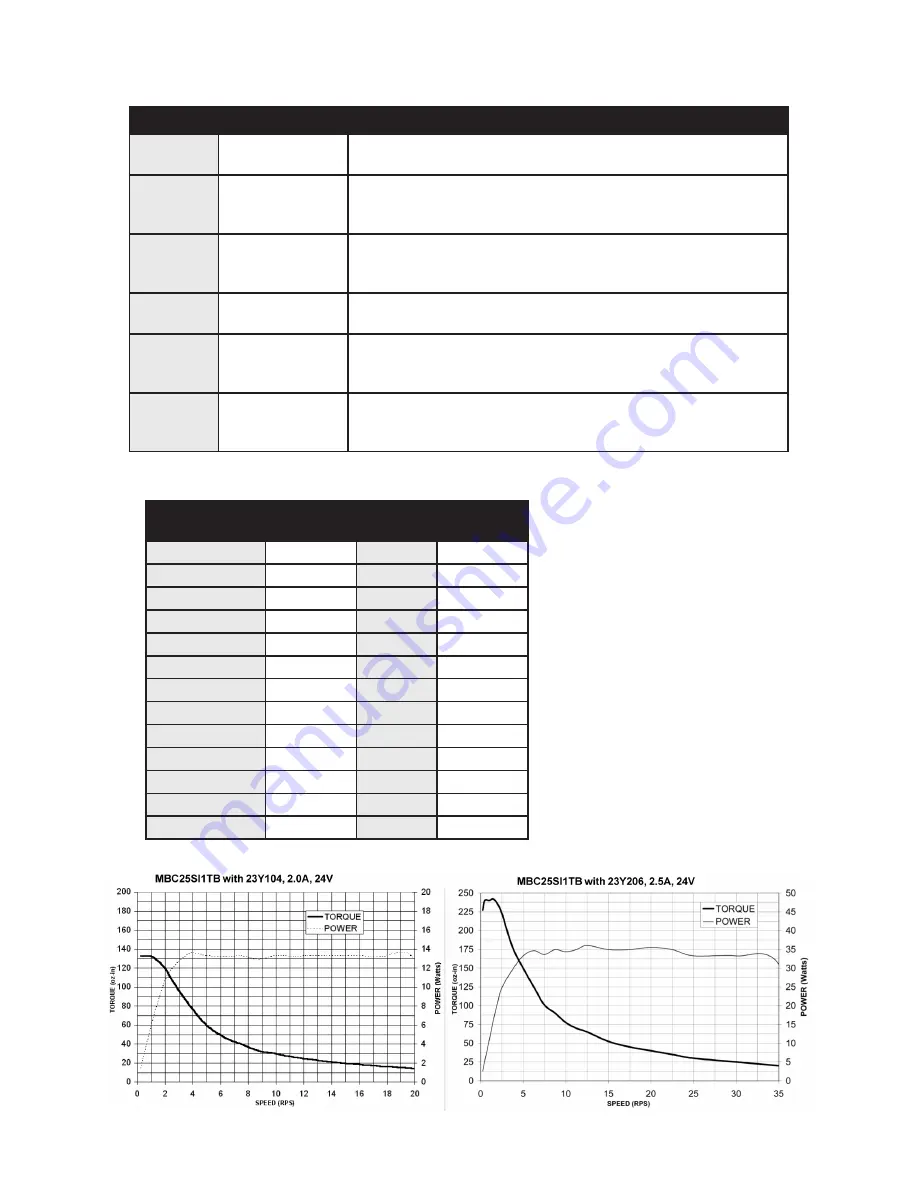
Torque Speed Curves
July 2018


