


Installation Guide
NXA-WC80211G/CF
Wireless 802.11g CompactFlash Card
Step 3: Close and Re-secure the MVP Panel Enclosure
Note
: When re-securing the enclosure, care must be taken not to pinch the antenna
wire in the housing.
1.
Reinstall the dark grey trim along the top rim of the board (
B
in FIG. 5).
2.
While angling the top rim of the MVP’s rear outer housing (
A
in FIG. 5) down
toward the IR Emitters, insert the four outer housing latches into their
corresponding attachment locations along the top rim of the MVP panel (two on
either side of the IR Emitters).
3.
While firmly holding the top rims together, gently press down on the bottom ridge
of the outer housing (at the latch locations) and verify that each housing latch fits
within its corresponding attachment location on the board. When done, complete
the insertion of the remaining housing latches.
4.
Verify that the notches along the bottom of the plastic battery slot separator strip
also fit into the three provided alignment holes on the circuit board.
5.
Firmly press down around the entire rim of the outer housing to snap the cover
back into place (FIG. 5).
6.
Use a grounded Phillips-head screwdriver to insert and re-secure the two
housing screws removed in Step 1 (FIG. 2).
7.
Insert any available batteries back into the battery compartment.
8.
Grab the battery cover and align it over the edges of the battery compartment.
Apply downward pressure to the traction grooves on the Battery Compartment
cover and slide it back towards the metal plate to reinstall the cover (FIG. 5).
Caution
: Once the Wireless CF Card has been installed, be careful opening the
MVP’s housing so that the CF card’s antenna (mounted to the inside of the bottom
housing) is not accidentally damaged or disconnected.
NXA-WC80211GCF Installation into Modero NXT Panels
Upgrading the wireless CF card in NXT-CV7/10 Table Top Touch Panels involves
removing the outer housing (with speaker plate), installing the new 802.11g wireless
card, and then placing the outer housing back onto the NXT panel, as described
below.
Step 1: Remove the Existing NXT Outer Housing
1.
Carefully detach all connectors from the rear of the touch panel and then gently
place the touch panel LCD facedown onto a soft cloth to expose the under-side
of the base (FIG. 6). This step helps prevent scratching of the LCD.
2.
Tilt the base forward so that both the bottom surface and Housing Screws are
easily accessible and then carefully remove the four plastic adhesive feet.
3.
While holding the outer housing and base plate at a 45° angle
(to prevent it from
sliding)
, use a grounded Phillips-head screwdriver to remove the four Housing
Screws (FIG. 6).
Note:
Reference the location of the four plastic adhesive "feet". Once the outer
housing is placed back onto the panel, these "feet" must be placed back in their
original locations so they can fit into their provided openings on a Battery Base.
4.
Rotate the panel back over (while gripping the entire unit and outer housing) and
rest the base back onto a flat surface.
5.
Gently tilt the LCD panel backwards to expose the Tilt Bracket/Speaker
assembly (FIG. 7).
6.
Locate the two screw holes at either sides of the front speaker grill and then use
a grounded Phillips-head screwdriver to remove the two Tilt Bracket Screws
(FIG. 7).
This procedure loosens the rear Tilt Bracket cover plate (
with the AMX logo and
Hinge brackets
) and provides greater flexibility for the removal of the outer
housing.
Without this step, the Hinge brackets present an obstacle to the
removal of the outer housing and restrict access to the circuit board.
7.
Tilt the LCD panel back up to gain better access to the Tilt Bracket cover plate.
8.
In a single motion
, carefully pull both the Tilt Bracket cover plate and outer hous-
ing up and then out (away from the LCD panel) to expose the internal circuit
board.
Step 2: Install the new 802.11g CF Card and Antenna (NXT)
1.
Discharge any static electricity from your body by touching a grounded metal
object and then locate wireless card slot on the main board (FIG. 8).
2.
Insert the tip of a grounded flat-head screwdriver into one of the card removal
grooves (located on either side of the existing CF card), and gently pry it out of
the slot. Repeat this process on the opposite card removal groove.
This alternating action causes the pre-existing card to "wiggle" away from the
on-board connector pins.
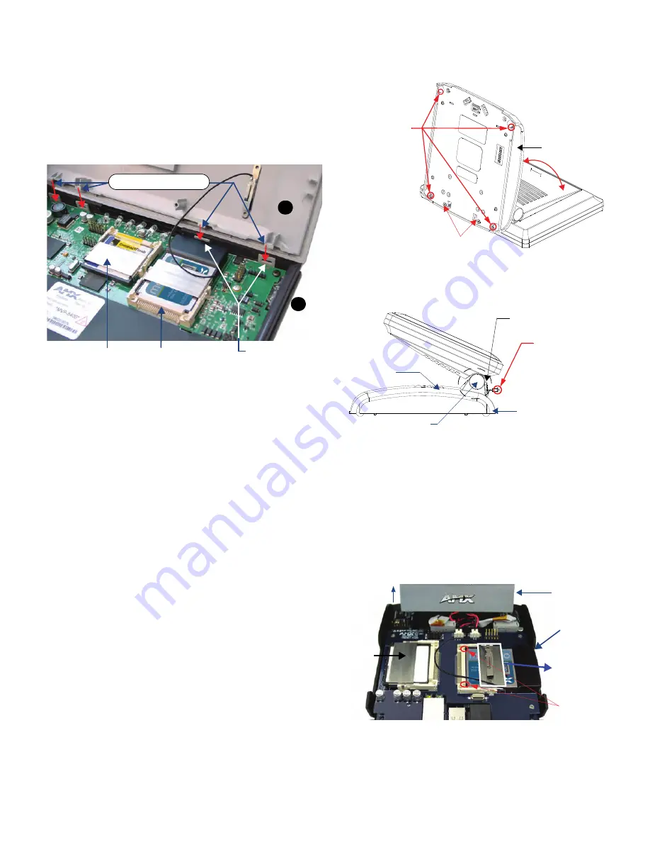
FIG. 5
Wireless CF card and outer housing latch attachment locations
4 outer housing latch
attachment locations
CF memory card
Wireless CF card
A
B
Outer housing latches (4)
FIG. 6
Location of the attachment screws underneath an NXT panel base
FIG. 7
Location of the attachment screws underneath an NXT panel base
FIG. 8
Location and orientation of the card slots (on both CV7/CV10 panel types)
Base
Unscrew these four
Housing Screws
to remove the
Circuit Board Cover
DO NOT REMOVE these screws
They secure the plastic base front cover.
45°
Outer Housing
Hinge Brackets (2)
Base
Tilt Bracket Screws (2)
These two screws must
first be removed before
being able to remove
the outer housing.
Tilt Bracket/Speaker assembly
Front of panel
Memory
Card
Tilt Bracket
Wireless CF Card
(Slot 2)
Card Removal
Grooves
CF metal plate
(with antenna
cover plate
shown installed)
(Slot 1)
page 3 of 6


