


The procedures for upgrading a CF card on an MVP is identical for both MVP-7500
and MVP-8400 panels. The procedures for upgrading/installing the new CF card are
also similar across all referenced NXT panels and NXD panels as a group
(differences arise from their housing)
.
NXA-WC80211GCF Installation into MVP Panels
Upgrading the wireless CF card on an MVP involves opening the panel enclosure,
removing the existing card, replacing it with the upgrade, and then closing the panel
enclosure, as described below.
Caution
: Batteries should be removed prior to upgrading the card.
Caution
: Discharge any static electricity from your body by touching a grounded
metal object
Step 1: Access the MVP’s Internal Components
1.
Carefully detach any connectors from the touch panel and then gently place
the MVP LCD facedown onto a soft cloth to expose the battery compartment.
This step helps prevent scratching of the LCD.
2.
Slide the Battery Compartment cover (FIG. 2) away from the metal plate to
expose the internal battery compartment (2 battery slots).
3.
Remove any previously installed MVP-BP batteries prior to removing the outer
housing.
4.
Use a grounded Phillips-head screwdriver to remove the two housing screws
shown in FIG. 2. Once done, place these screws aside.
5.
Grasp the bottom rim of the outer housing (just above the MVP interface
connector (
Blue arrows
in FIG. 2) and
in a single motion
, carefully pull the
bottom rim up and then out (away from the IR Emitter) to expose the internal
circuit board (
A
in FIG. 2).
It might be necessary to repeat this process along
the bottom and sides of the housing as well.
6.
Remove the dark grey trim from the top rim of the board (FIG. 2).
7.
After you have completed the upgrade process, complete the installation by
continuing to
Step 3: Close and Re-secure the MVP Panel
Enclosure
section on page 3
.
Step 2: Install the new 802.11g CF Card and Antenna (MVPs)
1.
Locate the wireless card slot on the main board (FIG. 3).
2.
Place the circuit board (
A
in FIG. 2) on a flat level surface so that the IR
Emitters are pointing away from you.
3.
Insert the tip of a grounded flat-head screwdriver into one of the card removal
grooves (located on either side of the existing CF card), and
gently
pry it out of
the slot. Repeat this process on the opposite card removal groove. This
alternating action causes the pre-existing card to "wiggle" away from the
onboard connector pins.
4.
Grasp the card by its sides, and then
carefully
pull it up and out from the slot.
An angular removal of the card is required because one of the housing’s latch
attachments blocks the slot opening.
5.
Flip over the MVP’s rear housing (
B
in FIG. 2) so that the internal support
structures are visible, and lay it directly in front of the circuit board such that the
battery compartment is furthest away from you. This placement provides
contact of both top rims (FIG. 3).
Note
: These surfaces must be properly cleaned to provide good adhesion for the
later installation of the wireless antenna.
6.
Place the included Mounting Template cutout along the bottom right corner of
the rear housing (FIG. 3). Use the housing’s inner support structures to fix the
template into place.
7.
Remove the new NXA-WC80211G CF card from it’s anti-static bag.
8.
Grip the sides of the new wireless card and insert it firmly into the slot opening
(
at a downward angle
) until the contact pins are completely inside the card
and securely attached to the pin sockets.
Note
:
You must precisely align the double-sided tape to the surface of the terminal
antenna’s metal plate in order to later secure the antenna within the pre-defined
installation area outlined by the included Mounting Template.
9.
Carefully peel-off one side of the included double-sided tape and adhere the
adhesive side to the surface of the antenna’s metal plate.
10.
Locate the
T
-shaped opening on the left of the cutout and make sure the
antenna wire is located along the left side of the cutout (FIG. 4).
11.
Grip the antenna by its sides and carefully peel-off the remaining protective film
on the double-sided tape.
12.
Align the antenna into the long vertical groove in the cutout and firmly adhere it
to the inner surface of the housing.
Make sure the wire is threaded along the
left side of the cutout, this helps in the removal of the cutout.
13.
With the antenna now securely attached to the MVP’s inner housing, remove
the cutout by carefully pulling up on the cutout and threading the antenna wire
through the
T
-shaped opening.
14.
To complete the upgrade process, close and re-secure the panel enclosure
using the procedures in the following step.
FIG. 2
Removing the MVP enclosure (housing)
Battery Compartment
Unscrew these
two housing
screws to remove
the circuit board
housing
cover
Bottom rim of
outer housing
This grey trim fits
inside the grooves
and around the
edges of the panel.
DO NOT
REMOVE
these screws.
They secure
the LCD.
Circuit board
housing
attachment
locations (4)
MVP outer
housing (rear)
A
B
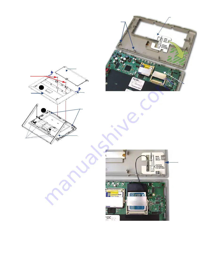
FIG. 3
Installing the Mounting Template in the correct location
FIG. 4
Adhering the antenna plate to the MVP outer housing
Internal
Support
Structures
Mounting Template
Wireless
Card
Slot
Mounting
Template
Cutout
page 2 of 6


