background image

Installation

7

Radia Lighting Control System

Mounting AMX Lighting Enclosures

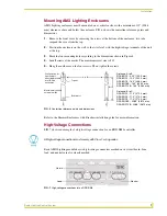
AMX Lighting enclosures must be mounted on a vertical surface with a minimum of 12" (304.8 

mm) clearance above and below the enclosure. FIG. 6 shows the centerline reference points and 

dimensions.

1.

Remove the front cover by removing the screws at the bottom of the enclosure; two tabs 

suspend the cover from the top.

2.

Position the enclosure on the wall so that it is level, with the high-voltage terminals of the unit 

at the top.

3.

Mark the four mounting holes according to the dimensions shown in Figure 8.

4.

Install screws at the marks. The maximum screw size is #12.

5.

Hang the enclosure on the four screws. Then, tighten the screws.

Refer to the Dimmer Enclosures with Breakers installation guide for more information.

High-Voltage Connections

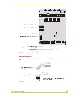
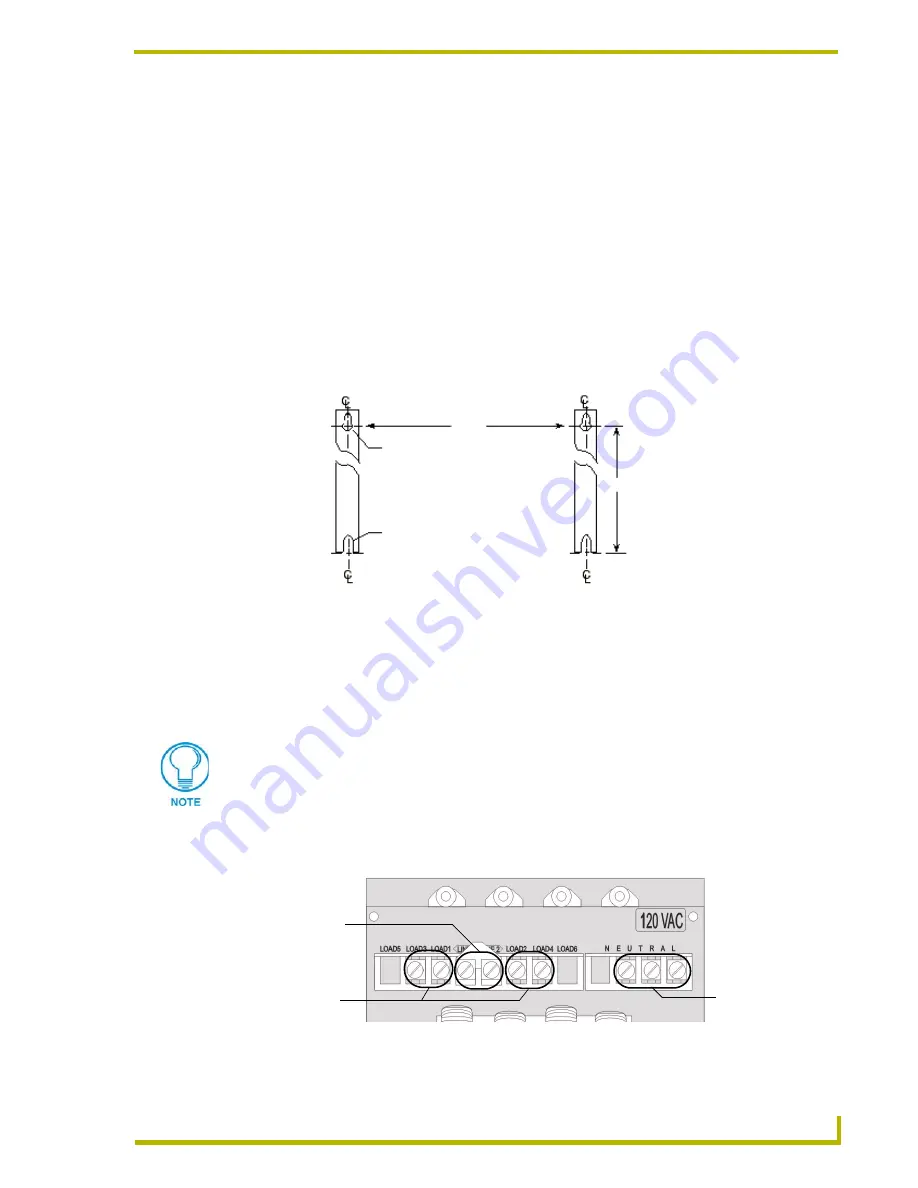
FIG. 7 shows an example of a high-voltage connection for an RDD-DM4 controller. 

Each AMX Lighting module has its high-voltage connectors marked on its circuit board. Line, 

load, and neutrals are also clearly marked.

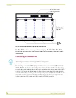
FIG. 6  

Center-line reference points and dimensions

A to B

B to C

Bottom slot

Top slot

Configuration for
right and left 
mounting brackets
for all Radia
enclosures.

Maximum mounting
screw size: #12

All high-voltage connections must comply with Class 1 wiring codes.

FIG. 7  

High-voltage connections for an RDD-DM4

Neutral

Load

Line in

Distance: B to C:
RDA-ENC2 - 11.0" (279.4 mm)
RDA-ENC4 - 11.0" (279.4 mm)
RDA-ENC6 - 11.0" (279.4 mm)
RDA-ENC6B - 22.88" (581.2 mm)
RDA-ENC12B - 22.88" (581.2 mm)

Distance: A to B:
RDA-ENC2 - 5.25" (133.3 mm)
RDA-ENC4 - 10.0" (254.0 mm)
RDA-ENC6 - 16.0" (406.4 mm)
RDA-ENC6B - 16.0" (406.4 mm)
RDA-ENC12B - 16.0" (406.4 mm)

Summary of Contents for RDA-ENC2

Page 1: ...instruction manual Lighting Controls Radia Lighting Control System Controllers Modules and Cards ...

Page 2: ... RMA is cancelled will be refused AMX is not responsible for products returned without a valid RMA number AMX Corporation is not liable for any damages caused by its products or for the failure of its products to perform This includes any lost profits lost savings incidental damages or consequential damages AMX Corporation is not liable for any claim made by a third party or by an AMX Dealer for a...

Page 3: ...Connecting high voltage three phase input power and loads 9 RDA ENC6B 120 208 VAC line input three phase 10 RDA ENC6B three phase line input connector reference 10 RDA ENC6 and RDA ENC12 power distribution and line input references 11 Installing RDM Modules into an Enclosure 11 Low Voltage Connections 12 Module connections 13 Green status LED indicator 14 Red status LED indicators 14 Configuring a...

Page 4: ...ii Radia Lighting Control System Table of Contents Glossary 21 ...

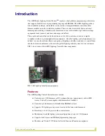
Page 5: ...lighting control requirements are defined you can choose from the extensive group of lighting controllers modules etc install them into the best suited enclosures and create the perfect lighting control system for your customers FIG 1 shows some of the AMX Lighting Control System components Features The AMX Lighting Control System features include Controls up to 1 500 dimmers or 255 6 channel devi...

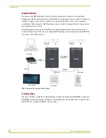
Page 6: ...on control systems Residential applications can be divided into inter linked lighting zones using central and local control configurations FIG 2 shows a sample AMX Lighting system configuration using PROlink dry closure and AXlink devices Controllers The four controllers available for AMX Lighting installations include the RDD DM4 4 channels RDD DM6 6 channels Integrated Dimmer Control Modules and...

Page 7: ...integrated dimmer control module 120 or 240 VAC RDD DM6 6 channel integrated dimmer control module 120 or 240 VAC Dimmer modules RDA CKM Dual Choke module 350 µS RDA PSM Power supply module RDM 2DC Dual VDR module 2400 W x 2 0 12 VDC RDM 2FDB Dual FDB module 2400 W x 2 RDM 2HSW Dual heavy duty switch module 2400 W x 2 RDM 2INC Dual incandescent dimming module 2400 W x 2 RDM 2MR Dual mercury relay ...

Page 8: ... modules Cont RDM MDM Multimode dimming module 2400 W 20 A RDM MR Mercury relay module 10 A RDM MR35 Mercury relay module 35 A RDM MR60 Mercury relay module 60 A RDM PR Peak relay module 2400 W RDM SWM Switch module 2400 W RDM ZC Zero cross module 2400 W RDM ZC50 Zero cross module 6000 W ...

Page 9: ...Install separate conduit for lighting loads The recommended knockout for loads is located on the top center of the enclosure Install separate conduit for the 120 VAC wiring to the line input terminal block The recommended knockouts for incoming power feeds are located on the top left and top right sides of the AMX Lighting enclosure Install separate conduit for low voltage signals for dry closures...

Page 10: ...ations FIG 4 RDA ENC2 RDA ENC4 and RDA ENC6 enclosure dimensions FIG 5 RDA ENC6B and ENC12B enclosures and dimensions Top View Internal View Bottom View RDA ENC2 RDA ENC4 RDA ENC6 Side View for all enclosures 12 0 304 8 mm 6 0 152 4 mm 0 75 19 05 mm 12 0 304 8 mm 6 0 152 4 mm 18 0 457 2 mm BOTTOM VIEW 457 2 mm SIDE VIEW RDA ENC12B RDA ENC6B 24 0 61 0 mm 24 0 61 0 mm Not included with enclosures TO...

Page 11: ...o the Dimmer Enclosures with Breakers installation guide for more information High Voltage Connections FIG 7 shows an example of a high voltage connection for an RDD DM4 controller Each AMX Lighting module has its high voltage connectors marked on its circuit board Line load and neutrals are also clearly marked FIG 6 Center line reference points and dimensions A to B B to C Bottom slot Top slot Co...

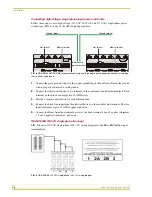
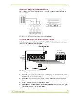
Page 12: ...utral wire for each dimmed zone 4 Connect the black line input from the electrical devices to the module s line terminal The line input terminal accepts a 10 AWG copper conductor 5 Connect load lines from the electrical devices to the Load terminals Load 1 applies to dimmer 1 Load 2 applies to dimmer 2 and so on RDA ENC6B 120 VAC single phase line input FIG 9 shows a 120 VAC single phase 2 W G wir...

Page 13: ...the copper ground lug on the enclosure Ensure the ground wire is properly connected to earth ground 2 Connect the white neutral wire s to one of the terminals on the enclosure s neutral terminal block 3 Provide a separate neutral wire for each controlled zone 4 Connect the black line input from the electrical panel to the enclosure s line terminal The line input terminal accepts a 0 AWG copper con...

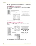
Page 14: ...agram for the RDA ENC6B line input terminal block RDA ENC6B three phase line input connector reference FIG 13 shows a sample RDA ENC6 three phase 4 W G line input connector and dimmer references FIG 12 RDA ENC6B 120 208 VAC three phase 4 W G wiring diagram FIG 13 RDA ENC6B three phase 4 W G line input connector and dimmer references 1 2a 2b 3 Line input 1 feeds dimmers 1 and 4 Line input 2a feeds ...

Page 15: ...he mounting slots The modules are positioned in the appropriate slot and secured using the supplied screws FIG 14 RDA ENC6 and RDA ENC12 power distribution and line input reference references RDA ENC6 Line input 1 feeds dimmers 1 and 4 Line input 2a feeds dimmer 5 Line input 2b feeds dimmer 2 Line input 3 feeds dimmers 3 and 6 RDA ENC12 Line input 1 feeds dimmers 1 and 4 7 and 10 Line input 2a fee...

Page 16: ...plied either by line power optional auxiliary power supply RDA PSM or the 12 VDC pin on the AXlink connector There is also a green status LED on the controller circuit board that blinks according to the current operating status of AXlink and red LEDs one for each of the external connectors for additional modules Figure 18 shows an example of the low voltage connections DIP switches and LEDs using ...

Page 17: ...link address DIP switch PROlink address DIP switch Module connector jack and LED CH5 Module connector jack and LED CH6 Dry contact closures AXlink connector and status LED PROlink connector Auxiliary power in 4 pin module connector on AMX Lighting controller 4 pin plug from RDM controller module Pin 4 GND Pin 3 RLY Pin 2 DIM Pin 1 12V 3 1 The 4 pin plug from the module connects to a 4 pin connecto...

Page 18: ...SW2 sets the PROlink pack number The pack number is determined by the value of all the switch position settings The following table shows the SW2 DIP switch positions and their values The pack number assignment range is 1 through 10 The lighting system will not work if you assign a pack number outside of the range 1 Power off the AMX Lighting enclosure at the breaker panel 2 Locate the SW2 DIP swi...

Page 19: ... interconnect two AMX Lighting RDD DM4 controllers and a PROlink wall panel FIG 18 PROlink wiring diagram FIG 19 PROlink configuration sample Radia PROlink connector PROlink wall panel 12V PR PR GND 12V PR PR GND PROlink Neutral Neutral HOT 1 HOT 2 orange PROlink connector RDD DM4 pack 2 connector orange PROlink PRO DP8 wall panel RDD DM4 pack 1 ...

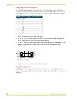
Page 20: ...the values shown in the proceeding table 3 Connect the four pin AXlink male connector into the four pin female AXlink connector on the controller circuit card FIG 20 shows how to wire the AXlink connector to a Central Controller system 4 Apply power to the controller module at the breaker panel Connecting dry closures AMX Lighting controller modules contain eight connections for dry contact closur...

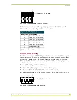
Page 21: ...set a AMX Lighting controller to default mode 1 Power off the AMX Lighting enclosure at the circuit breaker panel 2 Disconnect all AXlink and PROlink cables from the controller module 3 Connect a jumper to the dry contact closures 1 through 8 and to ground as shown in FIG 22 FIG 21 9 pin dry closure connector standard configuration Dry closure default presets Contact closure Default function 1 Cha...

Page 22: ... Reconnect the AXlink and PROlink connections 9 Power up the controller enclosure External power The following table lists the modules that use most of the operating power a AMX Lighting control module can supply They may require extra power from the AXlink connection or an external power supply connected to the control module or module s when using multiple modules If extra power is required conn...

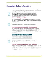
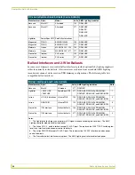
Page 23: ...sts DC Controlled Electronic Ballasts 4 Wire Ballasts The DC controlled Electronic Ballasts track a 0 10 or 0 12 VDC channel for dimming and an AC switch channel for on off This ballast design is better than magnetic but many stop dimming at about 20 brightness That s fine for energy management and secondary lighting zones but not for primary lighting that requires precision low level dimming cont...

Page 24: ...aces and 2 wire ballasts Manufacturer Style Model Volts AMX Lighting modules Note Advance Mark X All models 277 RDM INC Lightolier DA10 HDF DA20HDF PowerSpec HDF 277 RDD DM4 RDD DM6 RDM MDM RDM INC RDM 2INC and RDM INC50 1 Lutron HP 2 4 6 Interfaces HiLume FDB 120 RDD DM4 RDD DM6 RDM MDM RDM INC RDM 2INC and RDM INC50 2 Lutron GRX FDBI HiLume FDB 120 RDD DM4 RDD DM6 RDM MDM RDM INC RDM 2INC and RD...

Page 25: ...e CFL Lamp An acronym for Compact Fluorescent Lamp a type of fluorescent lamp Channel Radia Lighting The Radia Lighting processor s dimming engine recognizes six independent levels and paths of output control These control paths are called dimming channels or just channels Each Radia Lighting master controller pack has six channels of control AXlink channels are used in Axcess programming and appl...

Page 26: ...ry output of the transformer to reduce its voltage through electronic means Electronic transformers should be specifically designed for standard dimming Some electronic transformers are not dimmable or exhibit poor dimming performance Enclosure The UL approved box into which Radia Lighting control cards modules and accessories are installed Fade A steady change in lighting levels expressed in seco...

Page 27: ...ighting dimmer or switch designed for installation in a Radia Lighting enclosure Most modules are on a standard 2 75 x 10 enclosure plate or heatsink some modules require two standard spaces Neon A light source made from high voltage excitation of neon gas enclosed in a glass tube Neon is a type of lamp that uses a step up transformer to operate the lamp Neon transformers can be dimmed Pack A Radi...

Page 28: ...t to right starting at 1 This is used to describe which space in an enclosure a module is located or installed Solid State Dimmer A type of dimmer that uses electronic semiconductors and other solid state electronic devices to control the dimming of a lamp or ballast Space An enclosure dimension of 2 75 x 10 capable of installing a Radia Lighting module Switch A device that breaks and connects an ...

Page 29: ...Glossary 25 Radia Lighting Control System ...

Page 30: ... BELGIUM BRAZIL CANADA CHINA ENGLAND FRANCE GERMANY GREECE HONG KONG INDIA INDONESIA ITALY JAPAN LEBANON MALAYSIA MEXICO NETHERLANDS NEW ZEALAND PHILIPPINES PORTUGAL RUSSIA SINGAPORE SPAIN SWITZERLAND THAILAND TURKEY USA ATLANTA BOSTON CHICAGO CLEVELAND DALLAS DENVER INDIANAPOLIS LOS ANGELES MINNEAPOLIS PHILADELPHIA PHOENIX PORTLAND SPOKANE TAMPA 3000 RESEARCH DRIVE RICHARDSON TX 75082 USA 800 222...

Reviews: