

For warranty information, refer to www.amx.com.
8/08
©2008 AMX. All rights reserved. AMX and the AMX logo are registered trademarks of AMX.
AMX reserves the right to alter specifications without notice at any time.
3000 RESEARCH DRIVE, RICHARDSON, TX 75082 • 800.222.0193 • fax 469.624.7153 • technical support 800.932.6993 • www.amx.com
93-1044-001
REV: A
3.
Execute a test switch using the control panel (directions below).
Executing a Test Switch with the Control Panel
The primary enclosure in an Octaire system has a control panel on the front.
Control Panel Keys & Dial
•
Function Key – accesses start of Function menu at anytime during operation.
•
Select Key – enters selections.
•
Cancel Key – cancels an incomplete operation.
•
Take Key – must be pressed to complete an operation.
•
Control Dial – scrolls through the Function menu (starts with Change for
switching). Menu loops back to the first item after scrolling past the last item.
To execute a test switch:
1.
Press the Function Key.
2.
From the Function menu, press the Select Key to select Change.
The available Input and Output Keys turn blue.
3.
Press Input Key 1. Input Key 1 flashes white.
4.
Press Output Key 1. Output Key 1 illuminates white.
5.
Press the Take Key to execute the switch. Both keys turn blue.
After the test switch, attach the remaining source and destination devices.
Establishing Serial Control (if applicable)
The Octaire can be controlled by attaching an external control device/system
(e.g., a PC) to the serial port (DB-9), which supports AMX AutoPatch BCS (Basic
Control Structure) protocol.
To establish external serial control from RS-232 serial port:
1.
Plug the null modem cable (see FIG. 8 for pinout) into the serial port (DB-9) on
the primary enclosure (the one with the control panel).
2.
Plug the other cable end into the serial port on the serial controller/device (PC).
3.
Open serial communication software and set the port settings on the PC to
match the Octaire communication settings (baud rate = 9600, data bits = 8,
stop bit = 1, parity and flow control = none).
4.
Execute a test switch – enter the BCS command
CL0 I 1O1T
into a terminal
emulation program (e.g., HyperTerminal) to route Input 1 to Output 1 on the
ALL level. When
CL0 I 1O1T
appears, the switch is successful.
Establishing TCP/IP Control (if applicable)
TCP/IP control can be established to access the APWeb Server (which delivers
HTML pages and Java applets) to allow for remote control and diagnostics using
APWeb and PC-based Internet browsing software.
Requirements
•
PC – Windows XP Professional
©
, Windows 2000
©
, or Windows NT
©
;
web browser (e.g., Internet Explorer or Firefox); JRE v1.4.x or greater
(Java plug-in for APWeb’s XBar Controller).
•
Cable for PC – connect the Octaire directly to a network card in the PC
*
with a crossover (RJ-45) cable wired to TIA/EIA specification
TIA/EIA-568-A.
*
The TCP/IP port can be connected to a LAN; however, the cable requirements are
different. For details, contact your network administrator and see “APWeb – Initial
Setup by Network Admin” in the Octaire Instruction Manual.
To connect the Octaire
system to a PC network card:
1.
Insert one end of the crossover (RJ-45) cable (see “Requirements” above) into
a NIC card on the PC.
2.
Insert the other end of the cable into the TCP/IP port on the enclosure.
3.
Apply power according to the directions on the previous page (lower right).
4.
Check the indicator LEDs.
5.
Allow 20 to 60 seconds for discovery, then test the connection (see following).
To test the TCP/IP connection:
1.
Launch a browser on your PC.
2.
Type http://192.168.0.251 (the default APWeb IP address) in the address bar
of the browser and press Enter. The PC must be on the same subnet
(192.168.0.x); for details, see the Octaire Instruction Manual.
The Enter Network Password dialog box opens.
If the dialog box does not open, do a search for “APWeb troubleshooting” in the
Octaire Instruction Manual.pdf.
3.
Enter the case-sensitive default user name none / password none.*
Or
Enter the case-sensitive default admin user name super / password super.**
4.
Click OK.
APWeb opens.
5.
Execute a test switch – click the Controller link to open the XBar Controller;
click the blue crosspoint for Input 1 and Output 1 (the crosspoint turns red as
the switch is routed).
For setup and operation details, see the Octaire Instruction Manual.
* The default user name and password provide access to a limited set of server
pages for executing switches and macros.
** The admin user name and password provide access to the full set of server pages,
including pages for diagnostics, administration, and security.
Additional Information
Control Options
•
NetLinx
®
Compatible – supports Device Discovery; for specific control
programming information, contact your AMX representative.
•
APControl 3.0 (PC based) – see the AMX AutoPatch CD (included).
Important: Device Discovery functionality (beacon response) will only function
properly if the NetLinx master is connected to the RS-232 control port on the primary
enclosure (the one with the control panel).
The Octaire Instruction Manual
See instruction manual on AMX AutoPatch CD or at www.amx.com for following:
•
Additional control panel functions, e.g., verifying signals, adjusting audio,
and creating and executing global presets.
•
Using the custom label kit (included in shipment) for the control panel.
The Octaire Connector Guide / Vertical Interval Sync (VIS) Guide
This double-sided guide (included in shipment) provides important information for
cabling and linking enclosures and for connecting and enabling vertical interval sync.
Reference Document for the Octaire
The “BCS Protocol Instruction Manual” is on the AMX AutoPatch CD and at
www.amx.com.
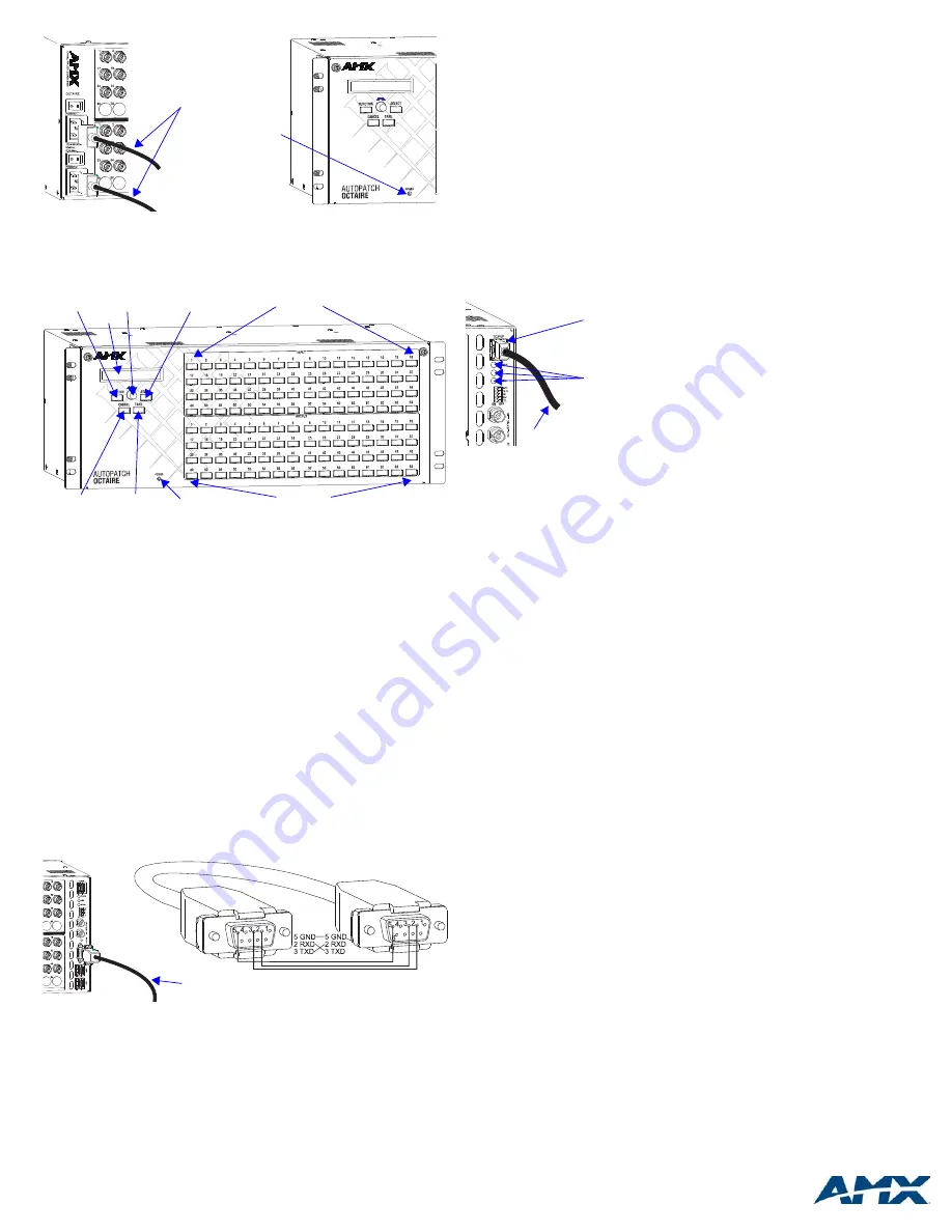
FIG. 6
Plug power cords into power receptacles
FIG. 7
Front view of Octaire enclosure with control panel
FIG. 8
Attach null modem serial cable (use pinout provided)
Power cords
Power indicator
Function Key
Control Dial
Select Key
Cancel Key
Take Key
LCD
Power Indicator
Input Keys
Output Keys
Null modem serial cable
FIG. 9
TCP/IP (RJ-45) connector
TCP/IP Indicator LEDs
Power: On - system is receiving power
Link: On - link status is active
Speed: On - speed status is 100 Mbps
Off - speed status is 10 Mbps
Note: The 2 small rectangular LEDs on
the RJ-45 connector are not used.
Indicator LEDs
TCP/IP (RJ-45) connector
To PC’s NIC card


