

For full warranty information, refer to the AMX Instruction Manual(s) associated with your Product(s).
10/08
©2008 AMX. All rights reserved. AMX and the AMX logo are registered trademarks of AMX.
AMX reserves the right to alter specifications without notice at any time.
3000 RESEARCH DRIVE, RICHARDSON, TX 75082 • 800.222.0193 • fax 469.624.7153 • technical support 800.932.6993 • www.amx.com
93-1311-01
REV: B
Daisy-Chaining KeyPads (AxLink)
To daisy chain the KeyPads with AxLink, both KeyPads would be connected to the AxLink
bus, and the RS232 is left unused. Either method can be used, but not a mixture of both.
Button Layout
FIG. 5 indicates the button layout for 8 and 16 button KeyPads:
•
8-Button KeyPads can be configured for button numbers 1-8, 9-16, 17-24, or 25-32.
•
16-Button KeyPads can be configured for button numbers 1-16 or 17-32.
Setting DIP Switches to Assign Alternate Button Numbering
Use the 2-position DIP Switch on the rear panel of the KeyPads to specify alternate button
numbers for each KeyPad, for cases in which you want to avoid having multiple KeyPads in
the same system using the same button numbers.
Note
: Multiple KeyPads are allowed to share identical button numbers.
Alternate Button Numbering: 8-Button KeyPads
The DIP Switch settings for 8-button KeyPads are described in FIG. 6:
Alternate Button Numbering: 16-Button KeyPads
The DIP Switch settings for 16-button KeyPads are described in FIG. 7:
Button Labelling
NOVARA ControlPads and KeyPads come with a set of clear plastic Key Caps, which are
designed to fit tightly over the pushbuttons, and allow you to place a label on each button
according to the requirements of your particular installation.
NOVARA ControlPads and KeyPads also come with a pre-printed acetate sheet with a
range of 50 (pre-cut) button label inserts. The button labels provided will accommodate
most installations, but it is also possible to print your own button labels on acetate for
custom button labelling.
Installing Acetate Button Labels and Key Caps - READ THIS FIRST!
1.
Punch out the desired Button Label from the included acetate sheet.
If you have printed your own custom button labels on acetate, cut each button label
to fit inside the Key Caps.
•
Custom button labels must be cut to a
1.20cm (0.472") square
to fit securely inside
the Key Caps.
•
The thickness of the acetate used must not exceed
.004”
(
0.10 mm).
2.
Place the Key Cap face-down, and insert the Button Label into the bottom of the Key
Cap (FIG. 8).
•
Orient the Button Label inside the Key Cap so that the two clips are located on the
left and right sides of the readable text on the Button Label, as indicated in FIG. 8.
•
Be sure to place the Button Label face-down inside the Key Cap (see FIG. 8), other-
wise the label will be seen in reverse once the Key Cap is installed.
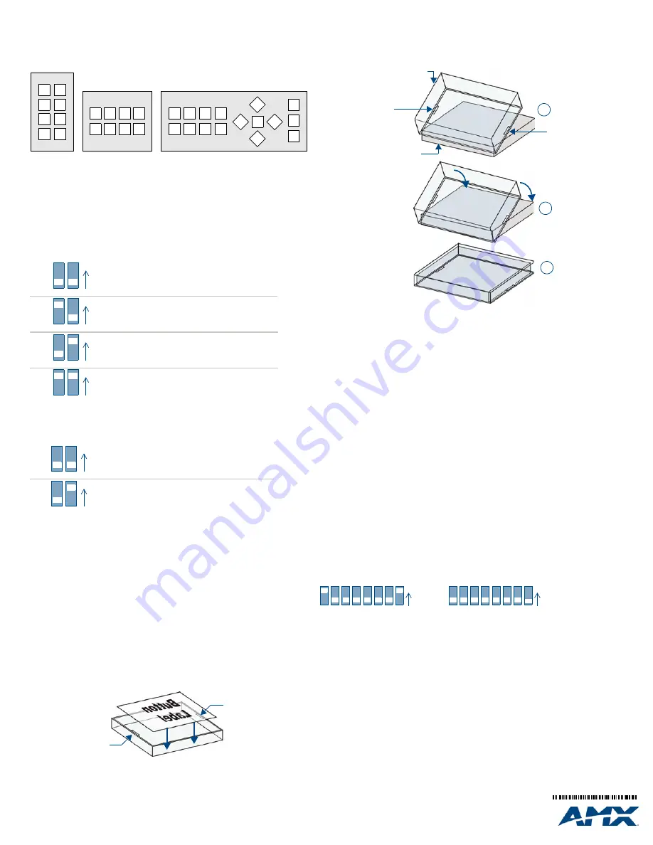
3.
Install the Key Cap on the pushbutton (FIG. 9):
Note
: Verify that the vertical orientation of the Button Label is correct relative to the keypad.
a. Gently press the bottom of the Key Cap (no clip) onto the pushbutton.
Do not allow the clips on either side to engage
.
b. With the bottom of the Key Cap secured, gently press the top of the Key Cap.
This action will engage both clips simultaneously, and the Key Cap will snap into
place on the push button.
Note
: Be careful to follow these procedures closely - the bottom of the Key Cap must be
installed on the pushbutton before the Key Cap clips engage, or there is a risk of the button
being misaligned.
Removing the Key Caps requires additional steps - refer to the NOVARA ControlPads
Operation/Reference Guide for details on Replacing Button Labels/Key Caps.
Setting the AxLink Address DIP Switch
The AxLink Device Address DIP switch determines whether this KeyPad will function as an
AxLink
device or as a Serial device.
If the DIP Switch is set to anything other than zero, this KeyPad will be assigned an AxLink
device address based on the switch settings.
Setting the AxLink Device Address
1.
If connected, disconnect the power supply.
2.
Locate the 8-position Device DIP switch on the rear panel.(FIG. 10).
3.
Set the DIP switch according to the switch values shown below.
The device number is set by the total value of DIP switch positions that are ON (up).
As an example, the first DIP switch in FIG. 10 defines device number 129
(1+128=129).
If you later change the device number, remove and reconnect the AxLink power connector
to enter the new device number into memory. Use AMX’s Dip Switch2 application (available
for download from www.amx.com) to assist in calculating Dip switch position values.
Additional Documentation
Refer to the NOVARA ControlPads Operation/Reference Guide (available at
www.amx.com) for additional installation details, configuration and RS232 control
instructions.
FIG. 5
KeyPads Button Layout
FIG. 6
DIP Switch Settings - Alternate Button Numbering: 8-Button KeyPads
FIG. 7
DIP Switch Settings - Alternate Button Numbering: 16-Button KeyPads
FIG. 8
Placing a Button Label inside a Key Cap
1
2
3
4
5
6
7
8
15
13
14
12
16
9
10
11
1
2
3
4
5
6
7
8
1
2
3
4
5
6
7
8
1
2
ON
1-8
9-16
17-24
25-32
1
2
ON
1
2
ON
1
2
ON
Switch 1-down / Switch 2-down = Buttons 1-8
Switch 1-up / Switch 2-down = Buttons 9-16
Switch 1-down / Switch 2-up = Buttons 17-24
Switch 1-up / Switch 2-up = Buttons 25-32
1
2
ON
1-16
17-32
1
2
ON
Switch 1-down / Switch 2-down = Buttons 1-16
Switch 1-down / Switch 2-up = Buttons 17-32
Acetate Button Label
Key Cap (face-down)
Clip
Clip
(face down)
FIG. 9
Placing a Button Label inside a Key Cap
Switch
1
2
3
4
5
6
7
8
Value
1
2
4
8
16
32
64
128
FIG. 10
Example Device DIP Switches
Clip
Clip
Pushbutton on keypad
Key Cap
- tilted so that the bottom
of the Cap is placed on the bottom
of the pushbutton first
At this point, do not allow the clips
on the sides of the Key Cap to engage
Press the top of the Key Cap
down to engage both clips at
once, securing the Key Cap
to the pushbutton
Once the clips are engaged,
the Key Cap is secured
to the pushbutton
1
2
3
5
6
ON
7
8
1
2
3
4
5
6
ON
7
8
1
2
3
4
Device Address = 129
Device Address = 0 (XPort)


