

For full warranty information, refer to the AMX Instruction Manual(s) associated with your Product(s).
1/09
©2009 AMX. All rights reserved. AMX and the AMX logo are registered trademarks of AMX.
AMX reserves the right to alter specifications without notice at any time.
3000 RESEARCH DRIVE, RICHARDSON, TX 75082 • 800.222.0193 • fax 469.624.7153 • technical support 800.932.6993 • www.amx.com
93-2105-08
REV: F
RS-232/422/485 wiring connector information
FIG. 3 shows the pinout and wiring specification information for the rear RS-232/RS-
422/RS-485 (DB9) Device Ports. These ports support most standard serial mouse
control devices and RS-232 communication protocols for PC data transmission.
The NI-3101-SIG uses Ports 1 - 6.
WARNING:
When wiring the 422/485 connections, do
NOT
use pre-made 9-wire
cable or connect the wire in the cable to any connection that will not be used by the
DB9 serial port. Only use wiring that connects the needed pins.
Ethernet 10/100 Base-T Connector
The RJ-45 Ethernet connector provides 10/100 network connectivity between the
panel and the NetLinx Master (FIG. 4).
Use a standard CAT5 Ethernet cable to provide communication between the
Integrated Controller and external NetLinx devices.
Ethernet Ports Used by the NI-3101-SIG
Preparing the NI-3101-SIG for Serial Communication
1.
Launch NetLinx Studio 2.x (default location is Start >
Programs >
AMX ControlDisc > NetLinx Studio 2 > NetLinx Studio 2
).
2.
When first connecting to the USB configuration port, follow the Windows®
instructions for installing the appropriate USB/Serial port driver.
3.
Select
Settings > Master Communication Settings
, from the Main menu, to
open the
Master Communication Settings
dialog.
4.
Click the
Communications Settings
button to open the
Communications Set-
tings
dialog.
5.
Click the
NetLinx Master
radio button (from the
Platform Selection
section) to
indicate you are working with a NetLinx Master.
6.
Click the
Serial
radio button (from the
Transport Connection Option
section) to
indicate you are connecting to the Master via a COM port.
7.
Click the
Edit Settings
button (in the
Communications Settings
dialog) to open
the
Serial Settings
dialog and set the COM port parameters to:
115.2K baud, N, 8, 1.
8.
Click
OK
to close the dialogs to return to the main application.
9.
Right-click the
Online Tree
tab entry and select
Refresh System
.
Once Serial communication has been established, use NetLinx Studio to configure
the Controller for Ethernet Communication, as described below.
Configuring the NI-3101-SIG for Ethernet Communication
Before continuing, complete the COM port steps above.
1.
Use an Ethernet cable to connect the Controller to the LAN to which the PC
running NetLinx Studio is connected.
Note
: NI-3101-SIG Controllers feature an Auto MDI/MDI-X Ethernet port. This
provides the option of using either a standard (straight through), or a crossover
Ethernet cable to communicate with a PC - both cable types will work.
2.
Select
Diagnostics
>
Network Address
from the menu bar and enter the
System, Device
(0 for a Master
), and Host Name information.
3.
To configure the Address:
•
Use a DHCP Address by selecting the
Use DHCP
radio button, then click the
GET IP
button (
to obtain a DHCP Address from the DHCP Server
), click the
SET IP Information
button (
to retain the new address
), and then finish the pro-
cess by clicking the
Reboot Master
>
OK
buttons.
•
Use a Static IP Address by selecting the
Specify IP Address
radio button,
enter the IP parameters into the available fields, then click the
SET IP
Information
button (
to retain the pre-reserved IP Address to the Master
), and
then click the
Reboot Master
>
OK
buttons to finish the process.
4.
Repeat steps 1 - 5 from the previous section, but rather than selecting the
Serial
option, choose
TCP/IP
and edit the settings to match the IP Address you
are using (Static or IP).
5.
Click on the
Authentication Required
radio box (
if the Master is secure
d) and
press the
User Name and Password
button to enter a valid username and
password being used by the secured Master.
6.
Click the
OK
to close all dialogs and return to the main application.
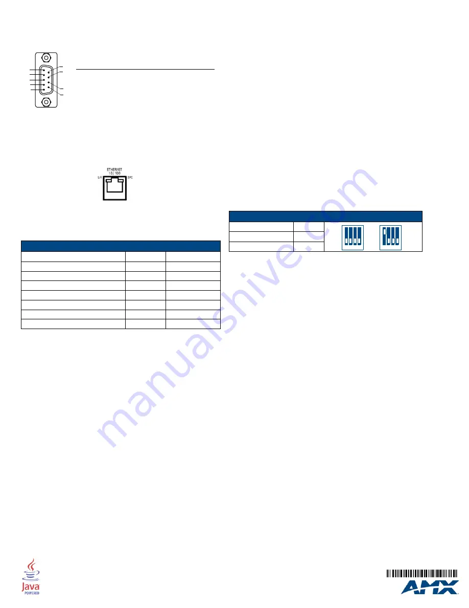
Setting the Configuration DIP Switch
The Configuration DIP switch is used to set the on-board Master to Program Run
Disable (PRD) mode, according to the settings listed in the table below:
The PRD mode prevents the NetLinx program stored in the on-board Master from
running during the device’s power-up. This mode should only be used if the resident
NetLinx program is causing inadvertent communication and/or control problems.
If necessary, place the on-board Master in PRD mode and use the NetLinx Studio v
2.x program to resolve the communication and/or control problems with the resident
NetLinx program.
After doing so, download the corrected program, reset the configuration DIP switch to
normal mode, recycle power, and try again.
Onboard WebConsole
NetLinx Masters have a built-in WebConsole that allows you to make various
configuration settings via a web browser on any PC that has access to the Master.
The webconsole consists of a series of web pages that are collectively called the
"Master Configuration Manager".
Accessing the WebConsole
From any PC that has access to the LAN that the target Master resides on:
1.
Open a web browser and type the IP Address of the target Master in the
Address Bar.
2.
Press Enter to access WebConsole for that Master. The initial view is the
WebControl
page.
Additional Documentation
Additional Documentation for the N1-3100 is available at www.amx.com:
•
Refer to the
NXI-x100 Series Hardware Reference Guide
for additional details
on Installation, Upgrading, and Wiring the NI-3100.
•
Refer to the
NI Series NetLinx Integrated Controllers WebConsole & Program-
ming Guide
for detailed configuration instructions.
FIG. 3
RS-232/422/485 DB9 (male) connector pinouts
FIG. 4
Layout of Ethernet LEDs
Ethernet Ports Used
Port type
Port #
Type
• FTP
21/20
TCP
• SSH (only
SSH
v2 is supported
)
22
TCP
• Telnet
23
TCP
• HTTP
80
TCP
• HTTPS/SSL
443
TCP
• ICSP
1319
UDP/TCP
• integration! Solutions
10500
TCP
5
4
3
2
1
9
8
7
6
DB9 Serial Port
pinouts (male connector)
Pin 2: RX signal
Pin 3: TX signal
PIN 5: GND
Pin 7: RTS
Pin 8: CTS
RS-232
Pin 1: RX -
Pin 4: TX +
PIN 5: GND
Pin 6: RX +
Pin 9: TX -
RS-422
Pin 1: A (strap to 9)
Pin 4: B (strap to 6)
PIN 5: GND
Pin 6: B (strap to 4)
Pin 9: A (strap to 1)
RS-485
SPD
- Speed LED lights (yellow)
100 Mbps and turns Off when the
speed is 10 Mbps.
when the connection speed is
L/A
- Link/Activity LED lights
(green) when the Ethernet
cables are connected and
terminated correctly.
PRD Mode Settings
PRD Mode
Position 1
• Normal mode (default)
OFF
• PRD Mode
ON
1 2 3 4
1 2 3 4
ON
ON


