background image

Installation

19

MXD/T-700 7" Modero X Series® Touch Panels

4.

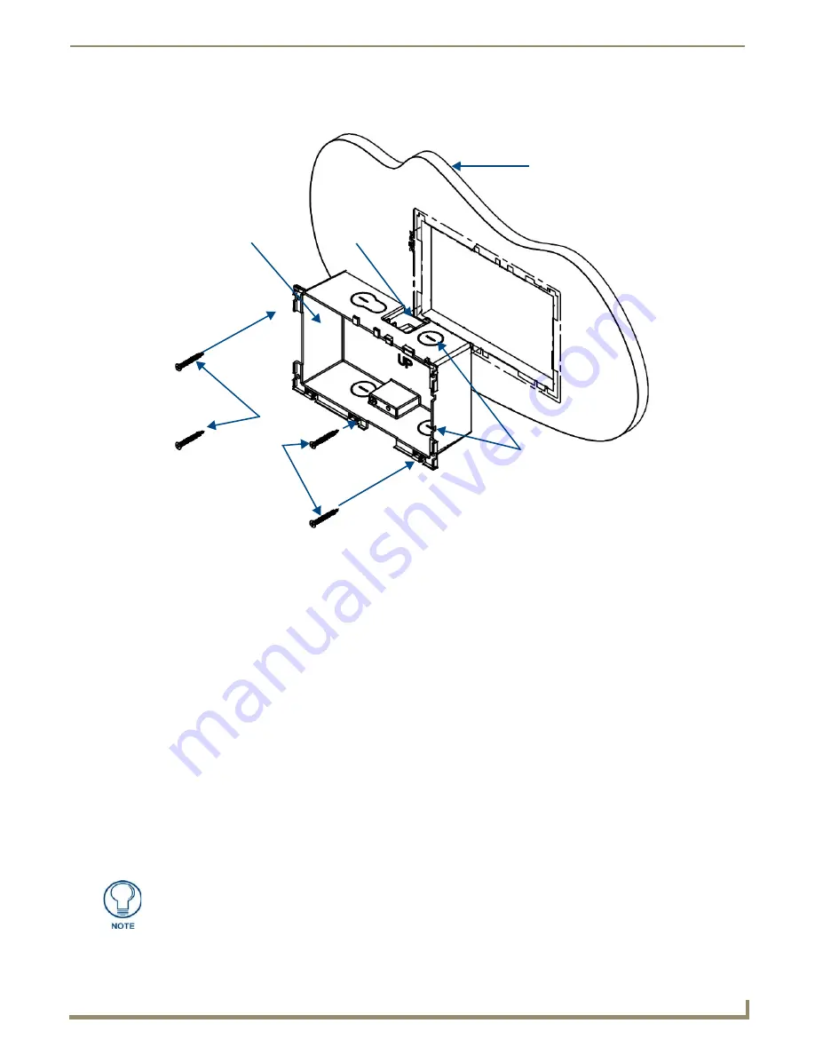
Thread the incoming Ethernet from their terminal locations through the surface opening (FIG. 19). 

Leave enough 

slack in the wiring to accommodate any re-positioning of the panel. 

5.

Remove the back box knockouts (FIG. 19) and thread the incoming wiring through the knockout holes.To facilitate 
installation, thread the Ethernet cable through a bottom knockout (Landscape) or a right-side knockout (Portrait), 
and the USB cable through a top knockout (Landscape) or left knockout (Portrait) 

6.

Thread the incoming Ethernet and USB wiring (if USB access is desired) from the surface opening and through the 
knockouts.

7.

Push the back box into the mounting surface. Insure that the locking tabs lie flush against the back box and that the 
back box goes freely into the opening.

8.

Extend the locking tabs on the sides of the back box by tightening the screws inside the box until snug. Not all of 
the tabs must be extended to lock the back box in place, but extending a minimum of the top and bottom tabs is 
highly recommended. Apply enough pressure to the screw head to keep the box flush with the wall: this ensures that 
the locking tabs will tighten up against the inside of the wall.
The back box is clear to allow visual confirmation that the tabs have been extended and are gripping the wall, as 
well as in assisting with removal if necessary.

9.

For additional strength, #4 mounting screws (not included) may be secured through circular holes located at the left 
and right sides of the MXD-700 (FIG. 19). In order to prevent damage to the touch panel, make sure that these are 
flush with the back box.

10.

Insert each connector into its corresponding location along the back of the device (FIG. 15). To reach the RJ45 
connector, gently pull it from beneath the electronics cover (FIG. 16). Attach the Ethernet cable and gently push the 
connection back under the cover.

FIG. 19  

MXD-700 Back Box Installation (Landscape)

Knockouts

Back Box

Mounting Surface

Locking

Tab

#4 Screws

To facilitate connection of the RJ45 connector to the Ethernet cable, press the RJ45’s 
cable into the RJ45 cable clip to hold it in a stable position. Make sure to remove the 
cable from the cable clip before continuing the rest of the installation.

Summary of Contents for MXD-700

Page 1: ...Operation Reference Guide Touch Panels MXT D 700 7 Modero X Series Tabletop Touch Panel 7 Modero X Series Wall Flush Mount Touch Panel Last Updated 10 9 2013...

Page 2: ...ked on the outside of each box The RMA is valid for a 30 day period After the 30 day period the RMA will be cancelled Any shipments received not consistent with the RMA or after the RMA is cancelled w...

Page 3: ...PLIED WARRANTIES OF MERCHANTABILITY AND FITNESS FOR A PARTICULAR PURPOSE WITH REGARD TO THE AMX SOFTWARE THIS LIM ITED WARRANTY GIVES LICENSEE SPECIFIC LEGAL RIGHTS Any supplements or updates to the A...

Page 4: ......

Page 5: ...Operation 8 Powering on the MXD 700 8 Microphone 8 Audio Video Capabilities 8 MXD 700 NC 8 MXD T 700 Features 9 Picture View 9 Preview Mode and Normal Mode 10 Picture View Send Command 10 Configurati...

Page 6: ...Drive 25 Transfer the Firmware File From the Flash Drive to the Touch Panel 26 Upgrading from Previous Firmware 26 Returning to Factory Default Firmware 27 Upgrading Firmware Via NetLinx Studio 28 Vie...

Page 7: ...n between RF devices like exchanging data identities Enhanced Usability External phone connections via Bluetooth or USB and HD video streaming Graphic Leaps Bounds The Modero X Series includes some st...

Page 8: ...ouse The MXT 700 features a 7 3 x 4 8 186 mm x 122 mm 8 8 222 mm diagonal display with a viewable area of 6 05 x 3 54 154 mm x 90 mm 7 0 178 mm diagonal The device communicates via Ethernet 10 100 por...

Page 9: ...le 10 100 Base T RJ 45 connector for Ethernet connectivity and PoE Touch Panel Display Display Type TFT Active Matrix Color LCD with Fringe Field Switching FFS Wide viewing angle technology Display Si...

Page 10: ...udio Streaming File Formats WAV MP3 Intercom Full Duplex VoIP SIP v2 0 supported with AMX CSG Operating Environment Operating Temperature 32 F to 104 F 0 C to 40 C Storage Temperature 4 F to 140 F 20...

Page 11: ...e a panoramic control surface is needed to provide access to multiple functions simultaneously while remaining elegantly unobtrusive In residences they are perfect for kitchens home theaters or home o...

Page 12: ...eep Button Single button on edge of panel for placing panel in sleep mode for powering off the panel and for accessing the Settings Pages Microphone 42dB 3dB sensitivity FET microphone Speakers 4 ohm...

Page 13: ...ange 25 Maximum Range 5 Bluetooth HID Profile v1 1 Keyboard Mouse Support requires MXA BT Bluetooth Adaptor Video Streaming File Formats MPEG TS for MPEG2 HTTP for MJPEG Audio Streaming File Formats W...

Page 14: ...or video and audio conferencing capabilities This microphone is concealed by the casing Audio Video Capabilities The MXD 700 has the capability of displaying multiple JPEG and PNG files at one time Th...

Page 15: ...the MXT 700 will return to its default display page To start Picture View 1 Connect a USB drive to the device Picture View will automatically recognize all available images on the drive and start disp...

Page 16: ...d 60 seconds 6 The counter beneath the buttons displays the number of images currently uploaded by the MXT 700 versus the number detected on the USB drive Preview Mode and Normal Mode Picture View has...

Page 17: ...53 mm from the top edge When using an NFC device with the MXT 700 you should align your device s antenna with the center of the touch panel s antenna FIG 1 and FIG 4 Cleaning the Touch Overlay and Ca...

Page 18: ...should be connected to the RJ45 port on the cable attached to the device FIG 10 Ethernet Cable Installation and Modification In installations where you wish to conceal the Ethernet cable a hole at le...

Page 19: ...ECA5968 05 through the hole with the RJ45 connector on the other side of the installation surface from the device 5 Press the Ethernet cable back into the clamp Do NOT tighten the clamp at this time...

Page 20: ...filled volume such as with insulation or concrete as well as with a closed volume such as between studs in an otherwise finished wall The diagram shows how heat generated by the device or other devic...

Page 21: ...the back box FIG 14 This back box is removed when installing the device into a wall or when using the optional Rough In Box accessory FG039 18 Power Via Power Over Ethernet Power for the MXD 700 is su...

Page 22: ...box Back box knockouts Locking tab When installing the backbox make sure that the assembly is in the correct position and in the correct place Once the locking tabs are extended and locked into place...

Page 23: ...the plastic back box is 5 IN LB 56 N CM Applying excessive torque while tightening the tab screws such as with powered screwdrivers can strip out the locking tabs or damage the plastic back box FIG 1...

Page 24: ...top and bottom tabs is highly recommended Apply enough pressure to the screw head to keep the box flush with the wall this ensures that the locking tabs will tighten up against the inside of the wall...

Page 25: ...ds until the snaps click to lock it down 13 Reconnect the terminal Ethernet and USB to their respective locations on either the Ethernet port or NetLinx Master Do not disconnect the connectors from th...

Page 26: ...example carefully press into the access holes in either end of the molding FIG 22 until the snap is disconnected To facilitate the disconnection grasp the bottom of the panel Landscape or right side P...

Page 27: ...Installation 22 MXD T 700 7 Modero X Series Touch Panels...

Page 28: ...X Series Programming Guide Information on Settings pages panel configuration and programming is included in the Modero X Series Programming Guide available at www amx com Programming the MXT 700 and...

Page 29: ...Configuration and Programming 24 MXD T 700 7 Modero X Series Touch Panels...

Page 30: ...all mount if a USB extension was not already installed 2 Create a directory on the USB flash drive with one of the following names depending on the panel you are upgrading Note that the name must matc...

Page 31: ...the directions displayed on the popup 6 Once the panel reboots it will perform the firmware upgrade After the upgrade the unit contains the newly loaded version of firmware Upgrading from Previous Fir...

Page 32: ...ration page 2 From the Configuration page select Admin 3 From the Admin Configuration page select Install Firmware 4 In the Firmware Installation page select Factory 5 The Confirmation Dialog box FIG...

Page 33: ...ommunications Settings dialog FIG 28 3 Click on the NetLinx Master radio button from the Platform Selection section 4 Click on the Virtual Master radio box from the Transport Connection Option section...

Page 34: ...should now display the connection to the device The Connection Status Icon on the device may take up to five seconds to register the connection Viewing devices on the Virtual System 1 After the Commu...

Page 35: ...eyed out 7 Click the Reboot Device checkbox if it is not already checked This causes the touch panel to reboot after the firmware update process is complete 8 Click Send to begin the transfer The file...

Page 36: ...Upgrading Firmware 31 MXD T 700 7 Modero X Series Touch Panels Verify you have downloaded the latest firmware file from www amx com and then save the Kit file to your computer...

Page 37: ...Upgrading Firmware 32 MXD T 700 7 Modero X Series Touch Panels...

Page 38: ...reply with a connection failure instantly if it is not Without using the ping feature a connection may still be attempted but a failure will take longer to be recognized When connecting to a NetLinx...

Page 39: ...Appendix Troubleshooting 34 MXD T 700 7 Modero X Series Touch Panels...

Page 40: ...Appendix Troubleshooting 35 MXD T 700 7 Modero X Series Touch Panels...

Page 41: ...egistered trademarks of AMX AMX reserves the right to alter specifications without notice at any time It s Your World Take Control 3000 RESEARCH DRIVE RICHARDSON TX 75082 USA 800 222 0193 469 624 8000...

Reviews: