Installation
7
Mio Modero Device Family
To change custom buttons:
1.
If connected, disconnect the power supply.
2.
If connected to mounting frame, place a flathead screwdriver in the notch at the bottom right of the
Mio Modero, and pry the faceplate from the mounting frame.
3.
On the back of the faceplate locate the button access points, outlined with white circles. Using a
straightened paperclip, poke through the button access points until the buttons pop free.
4.
Snap the desired custom buttons into place. Be sure to note the orientation of the white insert on the
back of the button, the notch must be down. Insert the bottom of the button first and then push the
top into place.
5.
If the power supply was disconnected in
Step 1
, reconnect and return power to the device.
6.
Snap the faceplate on the mounting frame.
Be certain to reprogram the Mio Modero to match the new button arrangement; use KeypadBuilder to
assign the locations. See the
KeypadBuilder Instruction Manual
available at
www.amx.com
.
Mio Modero Prestige
The Mio Modero Prestige ships with sheets of common menu items and icons for creating inserts for
single and double buttons.
1.
If connected, disconnect the power supply.
2.
If connected to mounting frame, place a flathead screwdriver in the notch at the bottom right of the
Mio Modero, and pry the faceplate from the mounting frame.
3.
On the back of the faceplate locate the button access points, outlined with white circles. Using a
straightened paperclip, poke through the button access points until the buttons pop free.
4.
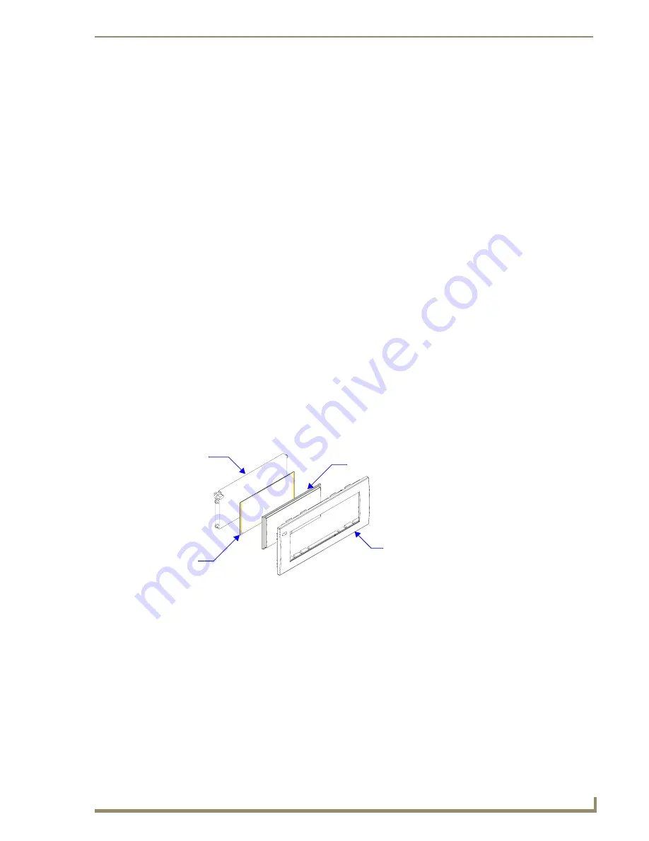
The Prestige buttons are comprised of three parts, the frame, window, and back insert. From the
front of the button, use your thumb to poke the window and back insert out of the frame. See FIG. 4.
5.
Snap the widow into the frame and then place the printed labels inside each
button.
6.
Snap the back inset to the window and frame.
7.
Insert the buttons into their proper location on the faceplate.
8.
If the power supply was disconnected in
Step 1
, reconnect and return power to the device.
9.
Snap the faceplate on the mounting frame.
FIG. 4
Prestige Button Components
Frame
Window
Printed
Label
Back Insert
Summary of Contents for Mio Modero Classic
Page 4: ......
Page 6: ...ii Mio Modero Device Family Table of Contents...
Page 10: ...Overview 4 Mio Modero Device Family...
Page 25: ...Mio Modero IR 19 Mio Modero Device Family FIG 16 Attaching the faceplate to the mounting frame...
Page 26: ...Mio Modero IR 20 Mio Modero Device Family...
Page 33: ...Programming The Mio Modero 27 Mio Modero Device Family...


