Installation
13
MXD/T-700 7" Modero X Series® Touch Panels
Installation
MXT-700 Installation
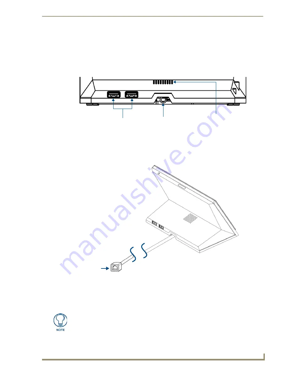
Any USB peripherals (mouse, keyboard, etc.) may be connected to one of the two USB ports on the rear of the
device (FIG. 9). Updates to the device’s firmware are also made via the USB ports.
Power via Power Over Ethernet
Power for the MXT-700 is supplied via Power Over Ethernet (PoE), utilizing an AMX-certified, capacitive
touch-compliant PoE injector or other approved AMX PoE power source. The incoming Ethernet cable should
be connected to the RJ45 port on the cable attached to the device (FIG. 10).
Ethernet Cable Installation and Modification
In installations where you wish to conceal the Ethernet cable, a hole at least 1.00” (2.54 cm) in diameter is
required in the surface to allow passage of the female RJ45 connector (FIG. 10). If using a smaller hole is
unavoidable, you will need to disconnect the Ethernet cable (
ECA5968-05
) from the device.
FIG. 9
Connectors on the rear of the MXT-700
FIG. 10
Back of the MXT-700, showing RJ45 port and cable for PoE
USB Ports
Entry for RJ45/
PoE Cable
Speaker
Cable length
edited for clarity
RJ45 Port
The minimum diameter hole through which the Ethernet cable may pass is 0.50"
(1.27 cm).
Summary of Contents for FG5968-04
Page 4: ......
Page 28: ...Installation 22 MXD T 700 7 Modero X Series Touch Panels ...
Page 30: ...Configuration and Programming 24 MXD T 700 7 Modero X Series Touch Panels ...
Page 38: ...Upgrading Firmware 32 MXD T 700 7 Modero X Series Touch Panels ...
Page 40: ...Appendix Troubleshooting 34 MXD T 700 7 Modero X Series Touch Panels ...
Page 41: ...Appendix Troubleshooting 35 MXD T 700 7 Modero X Series Touch Panels ...


