

For full warranty information, refer to www.amx.com.
01/08
©2008 AMX. All rights reserved. AMX and the AMX logo are registered trademarks of AMX.
AMX reserves the right to alter specifications without notice at any time.
3000 RESEARCH DRIVE, RICHARDSON, TX 75082 • 800.222.0193 • fax 469.624.7153 • technical support 800.932.6993 • www.amx.com
93-10-828
REV: B
Adjusting the Picture
This section includes information for adjusting the gain, peak, and skew to obtain a
sharp picture on the destination display. Volume can also be adjusted during the
procedure for adjusting skew.
Tip for Flat Panel LCDs:
For optimal results, press the auto-adjust button on the flat
panel LCD after using the adjustment options on the RX Module.
Test Image File
Test image files are provided on the
AMX AutoPatch CD
. File names begin with the
resolution (800x600, 1024x768, 1280x768, etc.) and end with “SkewPattern.”
• Turn the peak and gain potentiometers (watch the black & white pattern
and text) before and after skew adjustment for brightness and sharpness.
• Turn the Adjust knob for each color until the corresponding color bars
align with the color bars directly below them.
Gain & Peak
Gain and peak potentiometers on the RX can compensate for overall cable length.
Important:
Do not push or over-tighten the potentiometer when turning it.
To adjust the gain & peak:
1.
Optional – On the PC, open the test image file for the resolution of the source
signal.
2.
If the picture’s brightness needs to be increased or decreased, turn the Gain
potentiometer.
3.
If the picture is not sharp enough, turn the Peak potentiometer. (Increasing the
peak removes graininess.)
4.
Repeat Steps 2 and 3 after adjusting the skew according to steps below.
Skew & Volume
The adjust knob on the RX Module can be used to compensate for skew inherent in
UTP cable by adjusting the skew of the video signals. The knob also adjusts the
volume. A small screwdriver works well for turning and pressing the knob. The knob
does not have a mechanical start or stop point. If the LED blinks when the knob is
turned, the setting has reached its minimum or maximum.
The RX Module ships with factory-defined default settings of “no-skew delay” for the
skew on R, G, and B and to “unity gain” on the volume. Once the adjustment process
has been successfully completed and saved, the new settings replace the factory-
defined settings. The system will restore the new settings whenever power is cycled.
To abort the adjustment procedure at any time, hold the Adjust knob down until the
LED blinks 3 times and the RX Module reverts to its previous settings. Cycling power
on the module during the adjustment procedure will have the same effect. The
individual settings are not stored in memory until all adjustments (Steps 2-10 below)
have been made.
To adjust the skew & volume:
1.
Optional – Open the test image file on the PC.
2.
Press the Adjust knob.
The LED turns red, and the module is placed in Red Skew Adjust mode.
3.
Turn the Adjust knob clockwise or counter-clockwise.
The red color component shifts right or left.
4.
Press the Adjust knob.
The LED turns green, and the module is placed in Green Skew Adjust mode.
5.
Turn the Adjust knob clockwise or counter-clockwise.
The green color component shifts right or left.
6.
Press the Adjust knob.
The LED turns blue, and the module is placed in Blue Skew Adjust mode.
7.
Turn the Adjust knob clockwise or counter-clockwise.
The blue color component shifts right or left.
8.
Press the Adjust knob.
The LED turns white, and the module is placed in Volume Adjust mode.
9.
Turn the Adjust knob clockwise to increase volume or counter-clockwise to
decrease volume.
10.
Press the Adjust knob.
The LED turns off, and the module saves all of the settings.
If the LED alternately blinks red and green, see “Troubleshooting” above right.
Tip:
To adjust the volume without changing the skew settings, press the Adjust knob
until the LED turns white and then complete Steps 9 and 10 above.
Troubleshooting
LED Blinks Red & Green
• If the LED alternately blinks red and green, a configuration failure has
occurred.
• If the blinking happens when the Adjust knob is pressed to save (see
Step 10 in the skew adjustment procedure to the left), the system failed to
save the settings. Any adjustments just made are still in effect, but will be
lost the next time power is cycled.
To save the adjustments, repeat Steps 2, 4, 6, 8, and 10 (i.e., cycle the
colors until the LED turns off).
If the blinking happens when power is cycled, the system could not find valid settings
and reverted to the factory-defined default settings. Complete Steps 2 through 10
again.
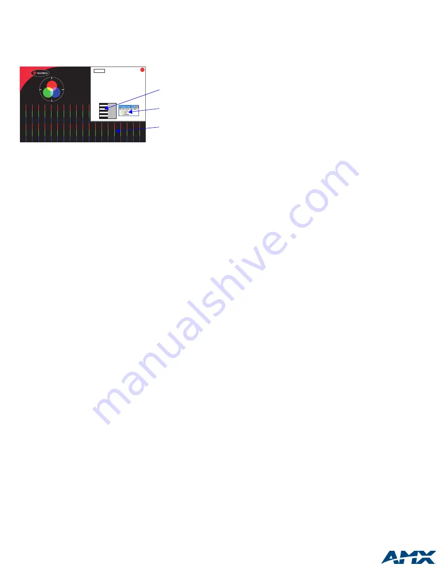
FIG. 5
Test Image file
Test Pattern for Cable Length
and Skew Compensation
NOTE: This Test Pattern must be viewed in Full Screen mode at 100%. Be sure the display
resolution matches the resolution shown in the box above in order to get accurate results when
making adjustments. If the Test Pattern has been resized since opening it, press Esc, then Ctrl+L
(full screen) followed by Ctrl+1 (100%).
1. Adjust the GAIN until the display is reasonably bright.
2. Adjust the PEAK until the black and white pattern is fairly balanced.
3. Press the Adjust knob to cycle through the Red, Green, and Blue color components. At each
color, the knob can be turned to adjust the skew delay if needed. When skew adjustments are
completed, the Red, Green and Blue color bars on this page should be perfectly aligned.
4. Press the Adjust knob (the LED turns WHITE) and turn to adjust the volume if needed.
5. Press the Adjust knob again to turn off the LED and save the settings.
6. Readjust the GAIN and PEAK to sharpen the Sample Text image below.
7. (Optional) If the destination is a flat panel LCD with an auto-adjust feature:
a. Use the up/down arrows or mouse wheel to scroll to page 2 of this Test Pattern.
b. Press the auto-adjust button on the display.
C. Once the auto-adjust is complete, scroll back to page 1 to make any final adjustments.
Ctrl+Q
to Exit
1280 x 768
Black & White Pattern
Sample Text
Color Bars


