


Chapter 1
8.
Specify the page length.
Menu Item
6 PAGE LGTH
FRONT TR
Check the fanfold paper size marked on the package.
9.
Perform trial printing after connecting the printer to the computer.
Adjust the tractors left or right to align the left print margin. Adjust
Menu Item “2 TOF ADJUST” to correct vertical alignment.
2 TOF ADJUST
FRONT TR
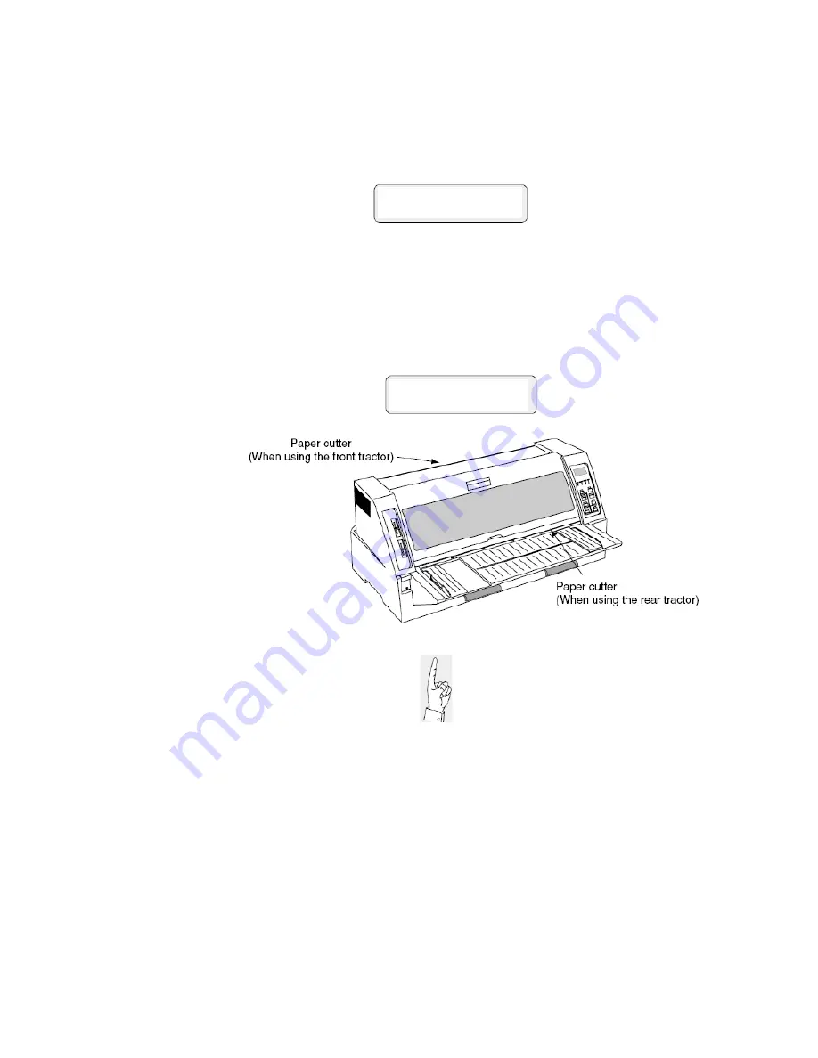
When using the front tractor along
with the CSF, cut the fanfold paper
by hand, not by the paper cutter.
Page 20 of 46


