background image

Chapter 1 

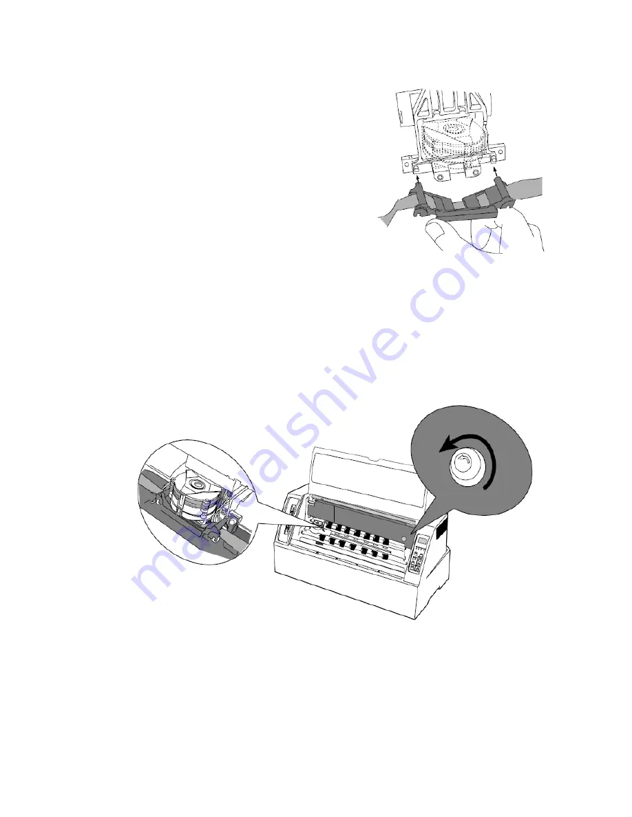
3.

  Fit the holes in the ribbon attachment 

to the right and left projections on the 
print head. 


Make sure that the ribbon is properly positioned under 

the edge of the print head. 


4.

 Turn the ribbon feed knob counterclockwise 

to remove any slack in the ribbon. 


Page 9 of 46 

Summary of Contents for Accel-7350

Page 1: ...Accel 7350 24 Pin Dot Matrix Printer User s Guide Document Number 130013 ...

Page 2: ...Assembly 10 Setting up the Manual cut sheet 14 Setting up the Front Tractor 17 Setting up the Cut Sheet Feeder optional 21 Installing the printer driver 26 Chapter 2 Control panel operation Control panel 27 Control panel view 27 Function keys 28 LCD 31 Lamps LED Indicators 32 Paper path lever 33 Head adjustment lever 34 Key shortcut functions 34 Chapter 3 Setup options How to use the setup modes 3...

Page 3: ... Out of paper cannot be detected 39 Not straight in vertical line printing 39 Incorrect charters printed 39 Unexpected printing results 40 How to solve the error message 40 Functional error message 40 Operational error message 41 Chapter 6 Specifications Printer specifications 44 Other specifications 45 Paper specifications 45 Options Consumables 45 Page 2 of 46 ...

Page 4: ...ce may not cause harmful interference and 2 this device must accept any interference received including interference that may cause undesired operation The manufacturer is not responsible for any radio or TV interference caused by unauthorized modifications to this equipment Such modifications could void the user s authority to operate the equipment ...

Page 5: ...gram is an international program that promotes energy saving through the use of computers and other office equipment The program backs the development and dissemination of products with functions that effectively reduce energy consumption It is an open system in which business proprietors can participate voluntarily The targeted products are office equipment such as computers displays printers fac...

Page 6: ...re included in the package and no parts are damaged Do not use the printer in a location exposed to direct sunlight or close to a heater or other heat generating device Do not use the printer in a dusty location or any location subject to sudden changes in temperature and humidity If any foreign matter gets into the printer turn off the printer immediately and remove the foreign matter If the case...

Page 7: ...Chapter 1 Page 6 of 46 Unpacking the printer The packing style is subject to change without notice ...

Page 8: ...ltage designated on the rating label on the back of the printer The AC outlet shall be installed near the printer and shall be easily accessible Connecting the printer to the computer 1 Parallel interface Make sure the power switch is turned to off Connect the signal cable to the printer and the computer 2 Serial interface Make sure that the power switch is turned to off Connect the signal cable t...

Page 9: ...front cover Move the print head to the left end position Caution Do not touch the print head immediately after printing because it may be too hot 2 Remove the Red Locking material located at the center of the ribbon cassette attach the cassette as shown below Page 8 of 46 ...

Page 10: ...on attachment to the right and left projections on the print head Make sure that the ribbon is properly positioned under the edge of the print head 4 Turn the ribbon feed knob counterclockwise to remove any slack in the ribbon Page 9 of 46 ...

Page 11: ...ear side 1 Attach the paper rack holders right left Press the holders until you hear a click When removing the paper rack holder use the remove lever located above the holder 2 Attach the paper rack to the paper rack holders 3 Lower the paper rack Snap the paper rack securely onto the holders Page 10 of 46 ...

Page 12: ... the mating connector on the rear side of the printer Then install the rear tractor 6 Both tractors can be moved right and left to meet the width of paper or printing data when the lock lever is released CAUTION Do not put your finger under the tractor cover Set fanfold paper onto the tractors Page 11 of 46 ...

Page 13: ... printer driver 8 Specify the page length 7 PAGE LGTH REAR TR Fanfold paper size marked on package Example When the page length is not specified refer to the number of sprocket holes to determine the page length No of holes x 0 5 inch equals the page length The above example 8 holes relates to 4 inch fanfold length Page 12 of 46 ...

Page 14: ...trial print sample after connecting the printer to the computer Adjust the tractors left or right to align the left print margin Adjust Menu Item 3 TOF ADJUST to correct vertical alignment 3 TOF ADJUST REAR TR Page 13 of 46 ...

Page 15: ...e paper rack holders right left and the paper rack Refer to Chapter 1 Installing Paper Rack Rear Tractor Assembly 2 Adjust the printing position by sliding the paper guide right or left When loading a wide paper adjust the right paper guide Page 14 of 46 ...

Page 16: ...ld be at AUTO when using the printer driver Auto Sheet Feed Rear Tractor Paper Rack Manual Front Tractor 4 Connect the printer to the computer and perform a trial printing The display appears as below along with the sound of a buzzer when the printer receives the data from the computer LOAD PAPER Page 15 of 46 ...

Page 17: ...matically NOTE If ske paper is extremely wed i e paper is over the not cas guide the printer may adjust the skew In this e move the paper guid then e to the left a little insert the paper at som pap e distance from the er guide In case of vertical offset the printing position should be adjusted by Menu Item 4 TOF ADJUST 4 TOF ADJUST MANUAL Page 16 of 46 ...

Page 18: ... printer as shown below Place the bottom of the holder into the chassis rotate the holder up until you hear a click 2 Insert the tractor connector left side to the mating connector on the front side of the printer 3 Attach the tractor to the paper rack holders as shown below Page 17 of 46 ...

Page 19: ...he holders as shown below 5 Both tractors can be moved right and left to meet the width of paper or printing data when the lock lever is released CAUTION Do not put your finger under the tractor cover Set fanfold paper onto the tractors Page 18 of 46 ...

Page 20: ... rack securely onto the paper rack holders 7 Slide the paper path lever to the appropriate symbol or the AUTO position The lever position should be at AUTO when using the printer driver Auto Sheet Feed CSF Rear Tractor Paper Rack Manual Front Tractor Page 19 of 46 ...

Page 21: ...orm trial printing after connecting the printer to the computer Adjust the tractors left or right to align the left print margin Adjust Menu Item 2 TOF ADJUST to correct vertical alignment 2 TOF ADJUST FRONT TR When using the front tractor along with the CSF cut the fanfold paper by hand not by the paper cutter Page 20 of 46 ...

Page 22: ... up the CUT SHEET FEEDER optional 1 Attach the paper rack holder right left and the paper rack 2 Move both paper guides to the right left end 3 Attach the hoppers and center support to the cut sheet feeder Page 21 of 46 ...

Page 23: ...se both hands and hold firmly at each end when lifting the cut sheet feeder Personal injury can occur if the CSF unit is dropped CAUTION NOTE Be sure to shuffle sheets sufficiently before l sheets time re setting them Otherwise severa of paper may be fed at the same sulting in a paper jam Page 22 of 46 ...

Page 24: ...et the CSF release levers to the front to release the paper bin 7 Set the paper guide lock lever to the Release position to adjust the paper width Set the paper guide lock lever to the Locked position Page 23 of 46 ...

Page 25: ...Set the CSF release levers to the back to close the paper bin 9 Slide the paper path lever to the symbol or the position of AUTO ASF The lever position should be at AUTO when using the printer driver Page 24 of 46 ...

Page 26: ...apter 1 10 Perform trial printing after connecting the printer to the computer In case of vertical offset the printing position should be adjusted by Menu Item 5 TOF ADJUST 5 TOF ADJUST CSF Page 25 of 46 ...

Page 27: ...on 3 Select the Local printer option and click the Next button 4 Select the desired printer port and click the Next button 5 From the Manufacturers list dialog click the Have Disk button 6 From the Install From Disk dialog browse to the location of the driver files and click OK 7 From the Install from Disk dialog the 7350 inf file should be displayed Select this file and click OK 8 Click OK from t...

Page 28: ...The liquid crystal display LCD on the control panel displays the processing conditions of the printer and the setting of the functions The keys on the control panel provide various functions 1 Control Panel view Page 27 of 46 ...

Page 29: ... if the keys are released The printer is reset immediately 3 SPEED Press the SPEED key to display the currently selected printing quality on the LCD Each press of the key to display the printing qualities in the following order LQ NORMAL HIGH 2 DRAFT 4 HIGH IMPACT Press the key to change the print mode Can open and close multipart print mode 5 MENU ALT MENU keys Press the ALT MENU key to enter the...

Page 30: ...erse Line Feed MENU Setup Menu RESET Resets the printer 8 TEAR OFF Press the TEAR OFF key and the printer automatically feeds the perforation of the paper to the paper cutter position for fanfold paper only If the perforation is not adjusted to the cutter position correct the position with the MICRO LF or MICRO RLF key The correct position is saved in memory and the perforation is fed automaticall...

Page 31: ... the paper When the EJECT LOAD key is pressed with no paper in the CSF mode the printer loads paper When it is pressed with paper loaded in the CSFmode the printer ejects the paper 10 LF Press the LF FF key to line feed in the forward direction at a pitch of 1 6 inch 11 MICRO LF ALT LF keys Press the MICRO LF key to line feed in the forward direction at a pitch of 1 360 inch Use this key to adjust...

Page 32: ...Chapter 2 3 LCD Current paper path and the User No are displayed Front tractor Manual Cut Sheet Rear tractor Cut Sheet Feeder Page 31 of 46 ...

Page 33: ...ting SPEED Green OFF NORMAL MQ speed printing FAST FLASH HIGH 2 High Speed Draft printing ON No paper is detected or other operational error occurred ERROR Amber OFF No error is detected Blinking A functional error has occurred such as home sense error Internal RAM error paper path switching error Head adjustment error park error and skew error ON Multipart printing HIGH IMPACT Green OFF Normal pr...

Page 34: ...ractor Cut Sheet Feeder The required paper path can be selected by the setting of the lever The paper path command is valid when selecting the AUTO The lever position should be at AUTO when using the printer driver Before changing the paper path remove the paper inside the printer by pressing the EJECT LOAD key Page 33 of 46 ...

Page 35: ... print head and the paper automatically 1 HEAD ADJUSTMENT In case that the graduation 1 7 is selected the gap between print head and paper is fixed Best position can be selected manually to meet the paper thickness as follows Graduation 1 for 1 sheet form Graduation 7 for 7 sheets multipart form Key shortcut functions Key shortcut functions are executed by pressing and holding the corresponding ke...

Page 36: ...ys are used to change the displayed menu They change only the display and do not change the setting The menu is changed rapidly when the or key is depressed and held for a second or more 3 Item selection keys These keys are used to change items displayed in a menu They change only the display and do not change the setting 4 ENTER key To select a displayed item press the ENTER key When the ENTER ke...

Page 37: ...y while depressing the ALT key 2 Select 6 with the or key 3 Press the key 4 Press the or key to display 8 INCH on the LCD 5 Press the ENTER key 8 INCH is marked with on asterisk 6 Press the MENU key The setting is automatically saved and the printer is initialized 1 HEAD ADJUSTMENT 6 PAGE LGTH FRONT TR 6 PAGE LGTH FRONT TR Page 36 of 46 ...

Page 38: ... Chapter 3 1 3 2 can be saved in each of the 6 User Formats Menu 18 PWR UP AS can be used to select one of the 6 User Formats as the Power Up Default The Power up user format is normally identified with a number on the LCD display as shown below Indicating the printer is set to User Format 1 as power up default Page 37 of 46 ...

Page 39: ...equate Adjust menu setting 1 HEAD ADJUSTMENT When multipart forms are used for printing Select ON menu setting HIGH IMPACT key 3 Paper jam often occurs Head Adjustment may not be adequate Adjust menu setting 1 HEAD ADJUSTMENT The thickness of paper may not be certain Select YES menu setting 45 LF STABILIZATION 4 Cut sheet paper is ejected as SKEW ERROR though paper is loaded straight manually Chec...

Page 40: ...nsors will cause erroneous errors Select NO menu setting of 34 PAPER JAM DETECTION in the SETUP mode 6 Out of paper cannot be detected In the case where printing is continued even when the paper is out the menu settings may not be adequate Verify the paper size the page length on SETUP and the format of the printing data 7 Vertical line printing is not straight Select BIDIRECTIONAL at the setting ...

Page 41: ...he page length of fanfold paper is not correct Set the paper length using menu setting 6 and 7 PAGE LENGTH The setting on the PC driver should also be checked The unexpected printing position occurs vertically after Out of paper Select PAGE END menu setting 32 PAPER OUT DETECTION How to solve the error message 1 Functional error message The functional errors mean that a serious error has occurred ...

Page 42: ...age indicates that fanfold paper is not fed back into the tractor assembly properly Cut the paper to remove it Fanfold paper is not set on the front tractor Install fanfold paper on the front tractor and press the ONLINE key Fanfold paper is not set on the rear tractor Install fanfold paper on the rear tractor and press the ONLINE key A cut sheet is not loaded into the printer Put a cut sheet on t...

Page 43: ...t head and the paper by menu 1 HEAD ADJUSTMENT When the paper thickness may be not constant set YES at menu 45 LF STABLE When the PAPER JAM appears despite no actual paper jamming set NO at menu 39 PAPER JAM DETECT A paper jam occurs at the rear tractor See the above column of PAPER JAM FRONT TR for troubleshooting Fanfold paper is not fed properly Remove the paper and reinstall the paper into the...

Page 44: ...ng the front cover will remove the cause of this error The printer is in the offline state while the cover is opened CAUTION Never open the front cover during printing Press the ONLINE key to stop printing and then open the front cover The jam sensor is defective when loading fanfold Press the ONLINE key to recover the printer from this error The paper jam detection function is disabled Remove pap...

Page 45: ...ft 400 CPS 10cpi SSD 600 CPS 15cpi Multipart printing Standard 1 5p DARK 1 7p Line feed speed 36 LPI Line feed pitch 1 360 INCH Paper path Front tractor or rear tractor Manual or notebook CSF option Head adjustment AUTO FIX Interface Parallel bidirectional IEEE 1284 nibble mode Serial Input buffer 64 k byte Emulation EPSON LQ 2550 IBM 2391 Other functions Barcode function Enlarged character Font t...

Page 46: ...th 8 15 Paper thickness 0 003 0 005 Paper quality Wood free paper Fanfold paper Paper width 8 15 multipart forms Number of sheet 8 or less Paper thickness 0 005 0 020 Paper quality non carbon equivalent Cut sheet paper Paper width 7 2 17 Manual mode Paper length 7 2 17 Paper thickness 0 003 0 005 Paper quality Wood free paper Cut sheet paper Paper width 7 2 17 multipart forms mode Paper length 7 2...

Page 47: ...AMT Datasouth Corporation 803 Camarillo Springs Road Suite D Camarillo CA 93012 1 800 215 9192 Page 46 of 46 ...

Reviews: