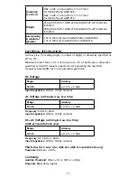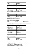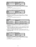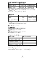
12
Measuring Resistance, Continuity and Diode
W
Warning
• To avoid false readings that can lead to electrical shock and injury, de-
energize the circuit before taking the measurement.
• To avoid electrical shock when testing resistance/continuity/diode in a
circuit, make sure the power to the circuit is turned off and all capacitors
are discharged. Use DC voltage function to check the capacitors are
discharged.
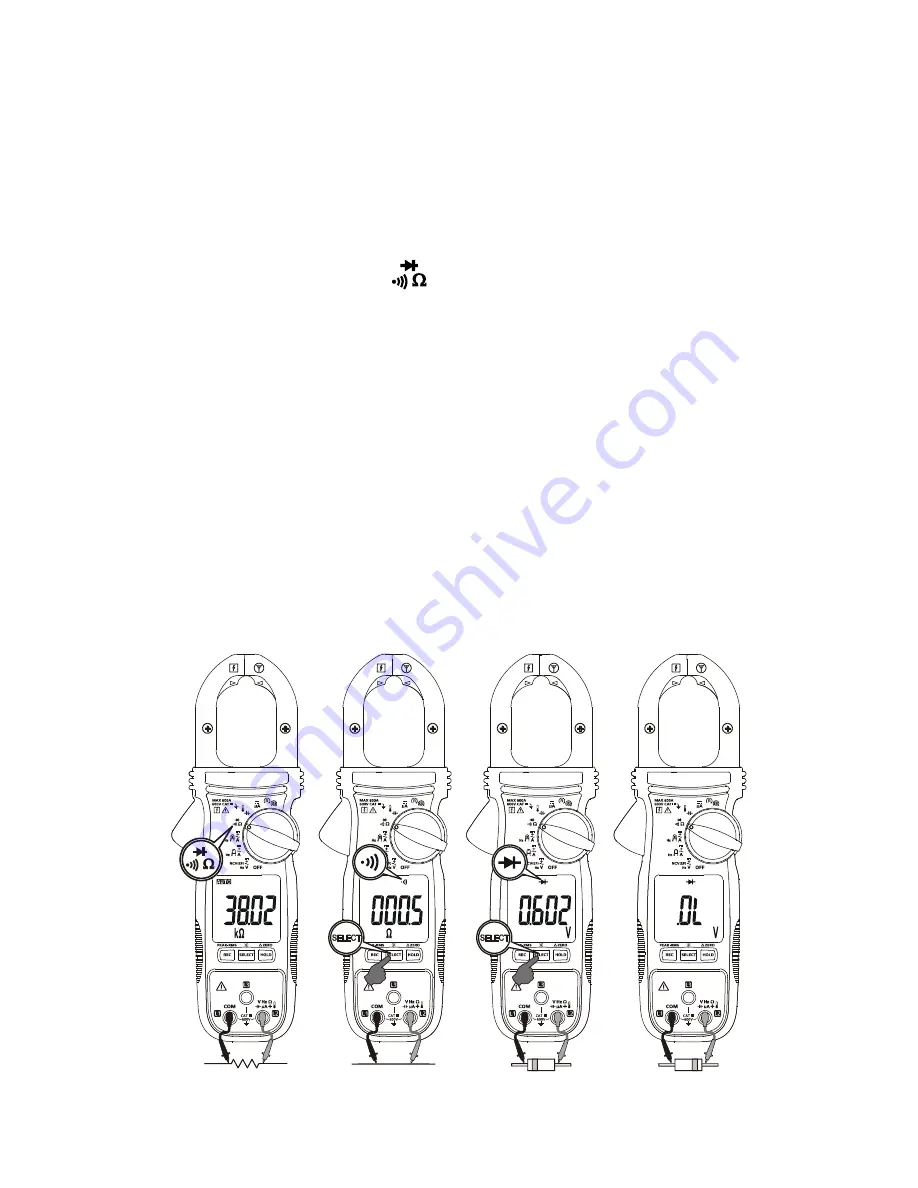
1. Connect the black test lead to the COM terminal and the red test lead
to the
Ω
terminal.
2. Turn the rotary switch to
.
3. Press SELECT button for desired measurement function.
4. Connect the probes across the circuit or component to be tested.
Resistance measurement:
The resistance reading appears on the display.
If the circuit is open or resistance exceeds the Meter’s range, the display
reads “OL”.
Continuity measurement:
If the circuit is shorted, the Meter beeps and
shows a reading
≤
10
Ω
. (Beeper ON
≤
10
Ω
, OFF > 250
Ω
) If the circuit is
open or resistance exceeds the Meter’s range, the display reads OL.
Testing diode:
When testing diode, normal forward voltage drop
(forward biased) for a good silicon diode is between 0.400V to 0.900V.
A reading higher than that indicates a leaky diode (defective). A zero
reading indicates a shorted diode (defective). Display reads “OL”
indicates an open diode (defective). Reverse the test leads connections
(reverse biased) across the diode. The display reads “OL” if the diode
is good. Any other readings indicate the diode is resistive or shorted
(defective).
Summary of Contents for AMP-210
Page 2: ......


