Chapter 3
Hardware
CoreModule 420
Reference Manual
39
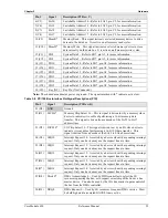
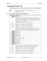
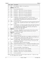
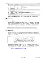
Table 3-17. Video Interface Pin/Signal Descriptions (J11)
Pin #
Signal
Description
1
TFTDCLK
TFT Shift Clock – This clock signal provides the timing for transferring digital
pixel data.
2
TFTDE
TFT Data Enable – This signal indicates valid data on any of the FP [23:0] lines.
3
TFTLP
TFT Line Pulse – This signal is the digital monitor equivalent of HSYNC.
4
TFTFrame
TFT Frame Marker – This signal is the TFT monitor equivalent of VSYNC.
5
GND
Digital Ground
6
GND
Digital Ground
7
NC
Not connected (FP0 = Panel Data 0)
8
NC
Not connected (FP1 = Panel Data 1)
9
FP2
Panel Data 2 – These pins (0 to 23) provides Digital pixel data output signals.
10
FP3
Panel Data 3 – Refer to pin 9, FP2, for more information.
11
FP4
Panel Data 4 – Refer to pin 9, FP2, for more information.
12
FP5
Panel Data 5 – Refer to pin 9, FP2, for more information.
13
FP6
Panel Data 6 – Refer to pin 9, FP2, for more information.
14
FP7
Panel Data 7 – Refer to pin 9, FP2, for more information.
15
NC
Not connected (FP8 = Panel Data8)
16
NC
Not connected (FP9 = Panel Data 9)
17
FP10
Panel Data 10 – Refer to pin 9, FP2, for more information.
18
FP11
Panel Data 11 – Refer to pin 9, FP2, for more information.
19
FP12
Panel Data 12 – Refer to pin 9, FP2, for more information.
20
FP13
Panel Data 13 – Refer to pin 9, FP2, for more information.
21
FP14
Panel Data 14 – Refer to pin 9, FP2, for more information.
22
FP15
Panel Data 15 – Refer to pin 9, FP2, for more information.
23
NC
Not connected (FP16 = Panel Data 16)
24
NC
Not connected (FP17 = Panel Data 17)
25
FP18
Panel Data 18 – Refer to pin 9, FP2, for more information.
26
FP19
Panel Data 19 – Refer to pin 9, FP2, for more information.
27
FP20
Panel Data 20 – Refer to pin 9, FP2, for more information.
28
FP21
Panel Data 21 – Refer to pin 9, FP2, for more information.
29
FP22
Panel Data 22 – Refer to pin 9, FP2, for more information.
30
FP23
Panel Data 23 – Refer to pin 9, FP2, for more information.
31
TFTEnVcc
TFT Power (Vcc) – This signal is the power to Flat panel displays.
32
TFTEnVee
TFT Voltage Enable (Vee) – This signal enables power to Flat panel displays.
33
+PNLVdd
Voltage (+3.3 or +5 volts ±5%) depends on setting of JP6.
34
+12V Out
+12 volts ±5%
35
GND
Digital Ground
36
GND
Digital Ground
37
HSYNC
Horizontal Sync – This signal is used for the digital horizontal sync output to
the CRT. Also used (with VSYNC) to signal power management state
information to the CRT per the VESA
DPMS
standard.
Summary of Contents for CoreModule 420
Page 1: ...CoreModule 420 PC 104 Single Board Computer Reference Manual P N 5001692A Revision A ...
Page 6: ...Contents vi Reference Manual CoreModule 420 ...
Page 10: ...Chapter 1 About this Manual 4 Reference Manual CoreModule 420 ...
Page 22: ...Chapter 2 Product Overview 16 Reference Manual CoreModule 420 ...
Page 50: ...Chapter 3 Hardware 44 Reference Manual CoreModule 420 ...
Page 64: ...Appendix A Technical Support 58 Reference Manual CoreModule 420 ...
Page 66: ...Appendix B Connector Part Numbers 60 Reference Manual CoreModule 420 ...
Page 70: ...Index 64 Reference Manual CoreModule 420 ...
Page 71: ......
Page 72: ......

