Chapter 3
Hardware
CoreModule 420
Reference Manual
19
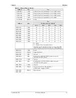
Table 3-1. Memory Map (continued)
Address
Size
Use
0400 0000
1MB
RAM or Unused if Framebuffer is set to 1MB or more
03F0 0000
1MB
RAM or Unused if Framebuffer is set to 2MB or more
03E0 0000
1MB
RAM or Unused if Framebuffer is set to 3MB or more
03D0 0000
1MB
RAM or Unused if Framebuffer is set to 4MB
03C0 0000
44MB
RAM
Use
Memory hole size selected
Address
Size
8MB
4MB
2MB
1MB
0MB
0100 0000
1MB
H
H
H
H
R
00F0 0000
1MB
H
H
H
R
R
00E0 0000
1MB
H
H
R
R
R
00D0 0000
1MB
H
H
R
R
R
00C0 0000
1MB
H
R
R
R
R
00B0 0000
1MB
H
R
R
R
R
00A0 0000
1MB
H
R
R
R
R
0090 0000
1MB
H
R
R
R
R
R = RAM
H = Memory Hole, forwarded to ISA
The board can be configured to have access to the 1MB
Flash anywhere in the memory hole, on 1MB alignment.
0080 0000
7MB
RAM
0010 0000
128kB
Shadowed BIOS
000E 0000
8kB
Unused
000D E000
8kB
DiskOnChip, if DC000-DDFFF window selected.
Unused if no DOC present.
000D C000
56kB
Unused
000C E000
8kB
DiskOnChip, if CC000-CDFFF window selected.
Unused if no DOC present.
000C C000
48kB
Unused
000C 0000
128kB
Unused, reserved for Video RAM, or
in SMI mode, mapped to RAM
000A 0000 -
0000 0000
640kB
Base memory
Summary of Contents for CoreModule 420
Page 1: ...CoreModule 420 PC 104 Single Board Computer Reference Manual P N 5001692A Revision A ...
Page 6: ...Contents vi Reference Manual CoreModule 420 ...
Page 10: ...Chapter 1 About this Manual 4 Reference Manual CoreModule 420 ...
Page 22: ...Chapter 2 Product Overview 16 Reference Manual CoreModule 420 ...
Page 50: ...Chapter 3 Hardware 44 Reference Manual CoreModule 420 ...
Page 64: ...Appendix A Technical Support 58 Reference Manual CoreModule 420 ...
Page 66: ...Appendix B Connector Part Numbers 60 Reference Manual CoreModule 420 ...
Page 70: ...Index 64 Reference Manual CoreModule 420 ...
Page 71: ......
Page 72: ......


