Ampcontrol Pty Ltd
– ABN 28 000 915 542
IPM V2 USER MANUAL
IPM2B003 Revision 15
– MAY/18
Uncontrolled Copy - Refer to Ampcontrol Website for Latest Version
Page 36 of 83
A
P
P
R
OV
E
D
FOR
E
X
T
E
R
N
A
L
D
IS
TR
IB
U
T
ION
–
P
R
OP
E
R
T
Y
OF
A
M
P
C
ON
TR
OL
P
T
Y
LTD
–
N
O
T
T
O
B
E
R
E
P
R
OD
U
C
E
D
I
N
P
A
R
T
and linear loads) practically achievable clearance times will be less than 200ms. In higher noise
applications (eg: Soft starters, variable speed drives and non-linear loads) higher clearance times up to
500ms may be necessary and can be shown to be safe.
Please note, excessive noise on the pilot-earth loop (as monitored by the EC protection relay) can be
indicative of a standing touch potential or another undiagnosed operating difficulty. Where EC trip
settings above 200ms are required to avoid nuisance tripping Ampcontrol recommends the source of
noise (and so the electrical distribution system design) is properly investigated to ensure the system is
safe.
7
CURRENT RELATED FUNCTIONS
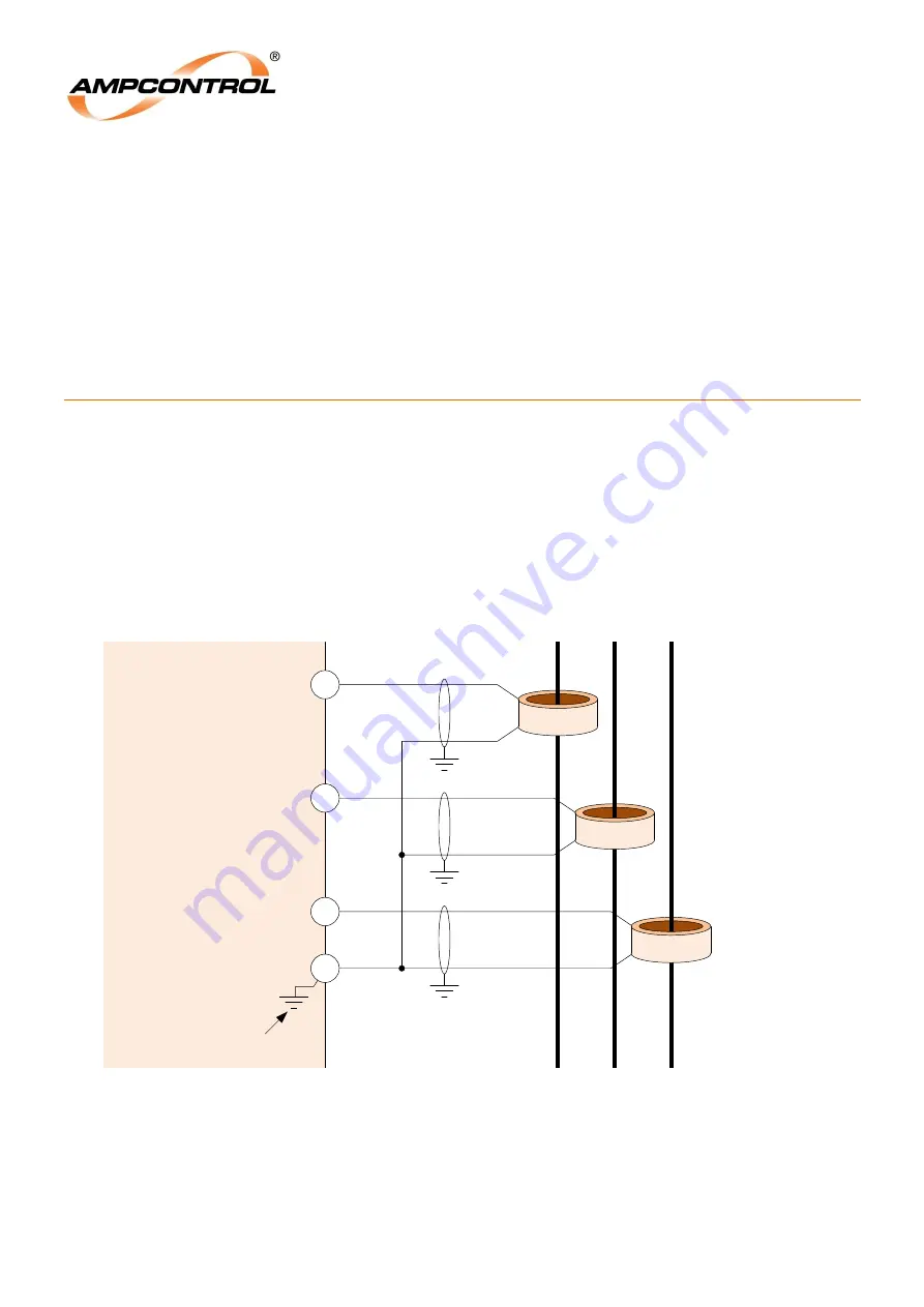
The IPM relay uses a current transformer on each of the three phases to monitor the line currents. The
measured currents are used to implement the following protection functions:
Overload Protection
Short Circuit Protection
Phase Current Balance
Residual Current Balance
Under Current Trip
Figure 7.1: IPM Phase CT Connections
A
B
C
Phase Conductors
Current TXF
1000/1 or
500/5
Current TXF
1000/1 or
500/5
IPM
Relay
CT-B
10
CT-A
9
S1
S2
P1
P2
S1
S2
P1
P2
CT-C
Current TXF
1000/1 or
500/5
11
12
S1
S2
P1
P2
Internally
Earthed
CT-COM


