15
PUMP INSTALLATION
Receiving pumps:
Visually inspect shipping crate(s)/pallet(s) for damage. Ampco pumps will be shipped in
boxes labeled Ampco Pumps or in crates. If there is any damage it is imperative to notify the
driver at the time of delivery. Failure to do so will make it difficult, if not impossible, to file a
damage claim and Ampco Pumps will not be held accountable. Please contact Ampco Pumps
shipping department with damage details ASAP.
Once unpacked, carefully inspect the pump for any damage that may have occurred during ship-
ping. Using a 15/16” socket, an extension drive and ratchet turn the impeller nut to make sure
the impeller turns freely. There should be a little noise from the seal which is normal. If there
is metal to metal contact when the impeller is turned shipping damage is likely. Leave the pro-
tective covers on the inlet and discharge connections until the pump is installed and is ready to
be connected to piping.
Pump location:
Install pump in an optimal location. Be sure that there is room around the pump so it can be
accessed readily for maintenance. Ensure that the motor has adequate ventilation. Make sure
the motor type is suitable for the environment in which it is installed.
Electrical installation:
Have a qualified electrician connect the motor using sound electrical practices. Do not test run
the motor with the pump dry. Mechanical seals can be damaged running dry even momentarily.
The pump must be flooded and the flush must be connected with flushing water flowing before
starting the pump. The pump and motor has been selected for a specific environment and sys-
tem application. Changing the environment or system conditions (i.e. change of fluid, change
in head losses, change in NPSHr) can overload the motor. When changing system conditions or
when in doubt, contact Ampco Pumps Company for technical assistance and someone will be
ready to assist.
Double seal flush:
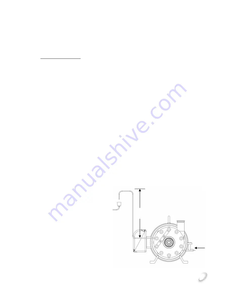
Install flush piping as shown in figure 23.
The regulating valve must be on the inlet end
of the flush. The flush requires 4-8 gallons
per hour at 1 BAR or 14.5 PSI. The tubing
on the exit side of the flush has a least 2 ft /
0.6m of height so once the flush has ran there
will be a small amount of water on the seal
and it will not run dry. Direction of flow
should always be from a lower elevation inlet
to a higher elevation outlet to evacuate air if
there is a difference in elevation.
Direction
of flush
Figure 23
2 ft
LF & LM SERIES PUMPS
Summary of Contents for LF 401
Page 1: ...Ampco Pumps LF LM Series Pump Instruction Maintenance Manual LF LM SERIES PUMPS ...
Page 4: ...4 LF LM SERIES PUMPS ...
Page 5: ...5 LF LM SERIES PUMPS ...
Page 7: ...7 LF LM SERIES PUMPS ...
Page 8: ...8 LF LM SERIES PUMPS EXPLODED ASSEMBLY LF PUMPS V550 X051 X151 X161 WITH THE 758 SEAL ...
Page 9: ...9 LF LM SERIES PUMPS ...
Page 10: ...10 LF LM SERIES PUMPS EXPLODED ASSEMBLY LF 401 PUMPS ...
Page 11: ...11 LF LM SERIES PUMPS ...


