AMOI LC26T E User Manual Download Page 5

-3-

Important Safety Instructions

17.Power Lines
An outside antenna system should not be located
in the vicinity of overhead power lines or other
electric light or power circuits, or where it can fall
into such power lines or circuits. When installing an
outside antenna system, extreme care should be
taken to keep from touching such power lines or
circuits as contact with them might be fatal
.
18.Overloading
Do not overload wall outlets, extension cords, or
integral convenience receptacles as this can result
in a risk of fire or electric shock.

19.Object and Liquid Entry
Never push objects of any kind into this product
through openings as they may touch dangerous
voltage points or short-out parts that could result in
a fire or electric shock. Never spill any kind of liquid
on the product.

20.Replacement Parts
When replacement parts are required, be sure the
service technician has used replacement parts
specified by the manufacturer or have the same
characteristics as the original part. Unauthorized
substitutions may result in fire, electric shock, or
other hazards.

21.Safety Check
Upon completion of any service or repairs to this
product, ask the service technician to perform
safety checks to determine that the product is in
proper operating condition.

22.Wall or Ceiling Mounting
The product should be mounted to a wall or ceiling
only as recommended by the manufacturer. Any
mounting of the product should follow the
manufacturer instructions, and should use a
mounting accessory recommended by the
manufacturer.

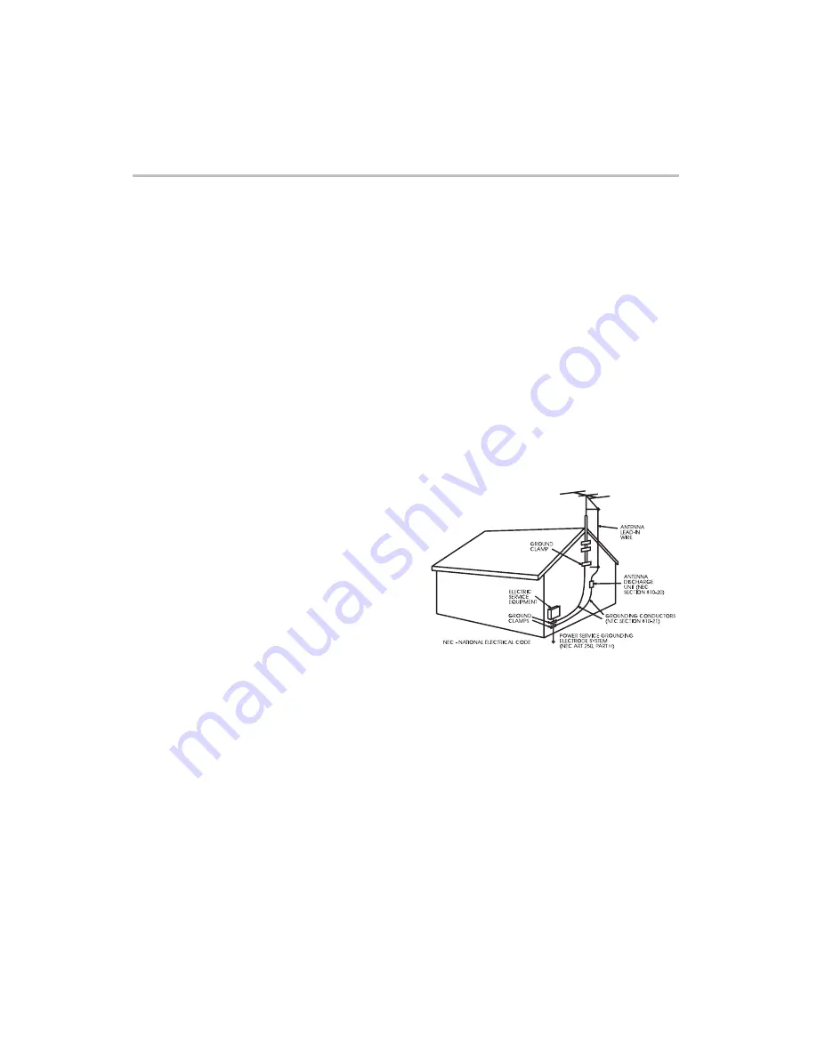
23.Outdoor Antenna Grounding
If an outside antenna or cable system is connected
to the product, be sure the antenna or cable
system is grounded so as to provide some
protection against voltage surges and built-up static
charges. Article 810 of the National Electrical Code,
ANSI/NFPA 70, provides information with regard to
proper grounding of the mast and supporting
structure, grounding of the lead-in wire to an
antenna discharge unit, size of grounding
conductors, location of antenna discharge unit,
connection to grounding electrodes, and
requirements for the grounding electrode. See
figure below.

Summary of Contents for LC26T E

Page 1: ...USER MANUAL LC26T E LC32T 1E 31 3...

Page 2: ...autions Important Safety Instructions i Front Panel Description ii Back Panel Description 26 27 29 30 Troubleshooting And Maintenance Display Mode Specifications i Antenna Connection ii YPbPr YCbCr co...

Page 3: ..._________________ DON T PLACE TO WET LOCATION Apparatus shall not be exposed to dripping or splashing with water and do not place objects filled with liquids on the apparatus such as vases This equipm...

Page 4: ...it into your outlet consult an electrician for replacement of the obsolete outlet 10 Protect the power cord from being walked on or pinched particularly at plugs convenience receptacles and the point...

Page 5: ...racteristics as the original part Unauthorized substitutions may result in fire electric shock or other hazards 21 Safety Check Upon completion of any service or repairs to this product ask the servic...

Page 6: ...This TV set shall be connected to a main socket outlet with a protective grounded AC power outlet Where to place the TV 1 Selecting where to place the TV Caution Select a place without direct sunlight...

Page 7: ...menu of the available viewing source MENU Press it to display the OSD menu The button also acts as select button OK in source menu CH VOL Press it to adjust volume The two buttons also act as directio...

Page 8: ...f Model LC32T31E VGA AUDIO IN EXT1 EXT2 ANTENNA 100 240 V 50 60HZ OPTICAL VGA IN COMPONENT IN POWER HDMI 1 IN HDMI 2 IN AV IN Rear interface Rear interface description Notes 1 The service only interfa...

Page 9: ...UDIO IN VGA IN EXT1 EXT2 ANTENNA OPTICAL HDMI 1 IN HDMI 2 IN COMPONENT IN AUDIO IN Video input S Video input Audio input Headphone Output Power Switch Side interface AV IN Notes 1 The service only int...

Page 10: ...AV FAV AUDIO FREEZE ASPECT VIDEO OFF VOG SUBTITLE 1 2 6 3 5 4 7 8 0 9 DUAL i Enter OSD setup mode Colour red green yellow blue buttons Standby button Main source Last source DTV TV Channel list Guide...

Page 11: ...A strong impact on remote control may damage it Signal from the remote con trol may be disturbed by sun light or other strong light In this case darken the room Point the remote control at the remote...

Page 12: ...er to the antenna jack on the TV When using 75 ohm round cable please do not bend the bronze wire it may make the video quality poor This type of antenna is commonly used in a house Bronze Wire Wall C...

Page 13: ...ress the OK button to confirm TV o buttons TV 11 Note Please refer to the illustration above to connect TV with DVD player or other component signal sources Connect the YPbPr YCbCr Cable and Audio Cab...

Page 14: ...ith S Video signal sources Connect S Video cable and audio cable to corresponding jacks of DVD player or other S Video signal sources Please choose S Video in the source menu when you connect DVD play...

Page 15: ...lect the desired signal type on Source Setting in the Setting menu only for EXT2 The setting will be stored and can be viewed on SOURCE menu See page 24 Please refer to page 11 How to select EXT1 EXT2...

Page 16: ...Pr Picture B C Please refer to page 11 When connecting with HDMI you can get better audio effect by connecting digital audio signal device to other playing devices like an amplifier through Optical co...

Page 17: ...ttons are the colour buttons on remote control This menu will display on the TV screen automatically after the TV being turned on for the first time Press Green button to choose to start Next 1 2 3 Se...

Page 18: ...Select two digit channel Press 1 9 to input the first digit and press 0 9 to input the second digit In TV mode press CH button to select next channel and press CH button to select previous channel CH...

Page 19: ...control to select the character Press the red button to delete the last character Press the green button to save Press MENU or EXIT button to get back Rename Channel Use direction buttons to select s...

Page 20: ...options of Dual setting in single picture is as follows The default setting of Dual is Mono if without signal Picture User 50 50 50 0 6 Picture Mode Brightness Contrast Colour Tint Sharpness ASPECT Pr...

Page 21: ...s MENU button to select Sound menu Press buttons to change the setting Press buttons to select sub items 1 2 3 Press EXIT button to quit A Press buttons to select Bass Treble Balance Simulated Stereo...

Page 22: ...lease set ff on the Skip Channel item the buttons On on the Skip Channel item CH O Menu Channel Menu Sound System Skip Channel Rename Channel Press MENU button to select Channel menu Press button to e...

Page 23: ...button to enter this menu 1 4 5 2 3 21 Channel Menu You can set TV program list with Auto Search function quickly Press the MENU button to select Channel menu Press the buttons to select Auto Search...

Page 24: ...l stop the channel will be saved with current channel number If the program is not your expected one please press buttons to continue the searching Press EXIT button to quit 1 3 2 4 5 Channel Menu Men...

Page 25: ...ess buttons to enter the menu Press buttons to select Phase Press buttons to enter the menu Press buttons to select Frequency To verify the H Position V Position Phase Frequency automatically The Auto...

Page 26: ...Press buttons to select Teletext Language Press buttons to select EXT 2 Press buttons to select Blue Screen 1 1 1 2 2 2 3 3 3 OSD Position Press MENU button to select Setting menu Press buttons to se...

Page 27: ...60 90 120 180 240 minutes Off For example The current time is 8 25 You can set the timer of 30 minutes Then the TV will be switched to standby mode in 8 55 automatically Sleep Timer Press MENU button...

Page 28: ...text page with puzzles riddles etc REVEAL COLOUR BUTTONS Red green yellow and blue field are shown at the bottom of the screen SUBPAGE Viewing of subpage Pressing the sub page button to enter the subp...

Page 29: ...uencies and bandwidth of PC or video source are TV compatible format with the 2 Check whether the TV set works is in mute mode 2 Ensure that the power switch is on 3 The contrast and the brightness ar...

Page 30: ...el logos and pricing displays especially if they are bright and stationary Moving or low contrast graphics are less likely to cause ageing of the screen Do not view for long periods of time using the...

Page 31: ...000 60 000 60 020 60 000 640X480 800X600 1280X960 1280X1024 1024X768 The interlace mode and SOG mode are not supported the H V Separated mode and H V Composited mode are supported HDMI DVI 480i 60Hz 6...

Page 32: ...30...

Page 33: ...the instructions means that your electrical and electronic equipment should be disposed at the end of life separately from your household waste There are separate collection systems for recycling in...

Reviews: