©Copyright AMKUS Rescue Systems, Inc. 2020
LAL-001 August 11, 2020 Rev01
10
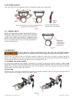
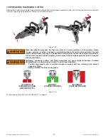
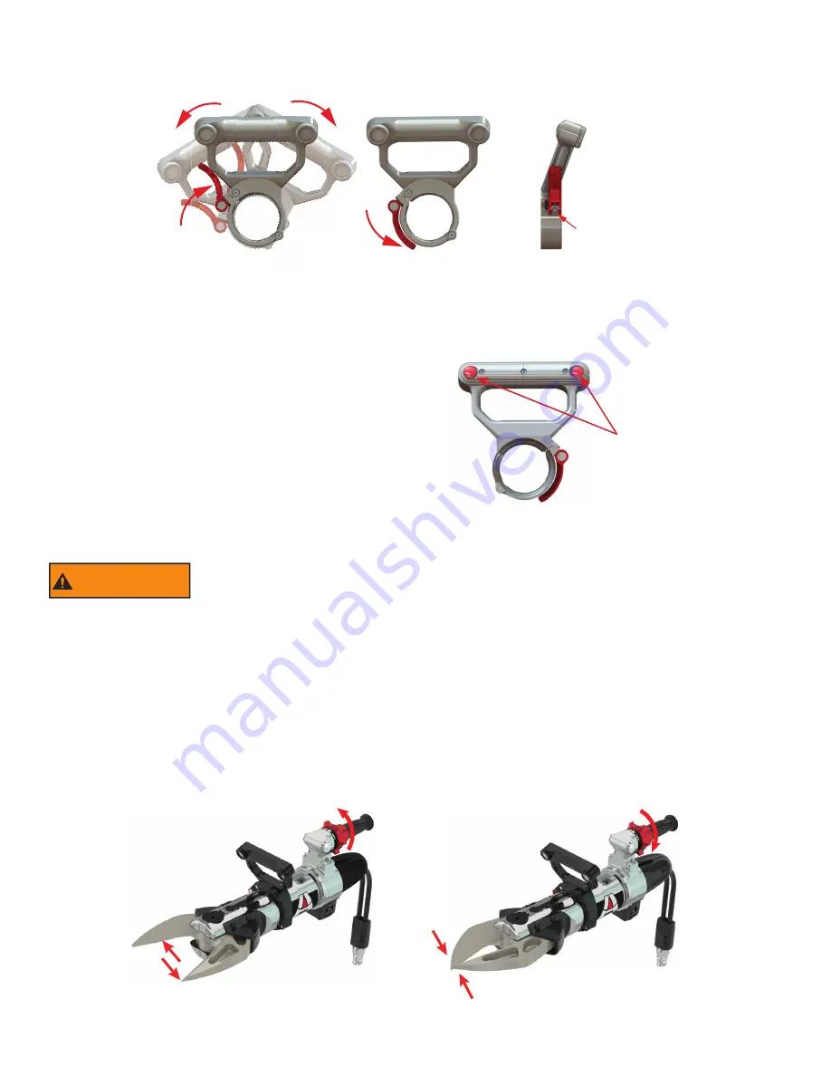
6.1 ROTATING HANDLE
Cutter and Combi Tools come equipped with a 360° swiveling handle that has variable tension.
RELEASE
LOCK
TENSION
SCREW
To increase rotating handle tension,
tighten the tension screw shown above.
Flip the red latch handle up on the tool’s cuff to rotate the rescue tool,
and flip it down to lock the handle position.
Figure 6.1
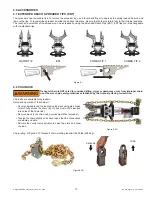
6.1.1 HANDLE LIGHTS
AMKUS dual handle lights operate at three levels of intensity. To
operate these lights, press the button located behind each light.
The lights can be powered OFF by scrolling through each setting
to OFF, or by a single button press from a setting that’s been
powered ON for over 5 seconds. Continuous use time is about 60
hours on low. Battery saver function will turn the lights o
ff
after 15
minutes of continuous use.
Button press:
1st light level low
2nd light level medium
3rd light level high
4th power off light
Figure 6.1.1
7.0 OPERATION
WARNING
Do not connect tools in series. Connecting tools in series could cause operational problems,
equipment failure, or catastrophic failure of the equipment resulting in serious injury or death.
Start the power unit (refer to power unit and engine manuals). Following the instructions in the power unit manual, operate the
selector valve to charge the hose line to which the tool is connected. Pick up the tool, noticing that the design of the cutter makes it
natural to grip the handle with one hand and the control valve hand grip with the other.
7.1 CONTROL VALVE ACTUATOR
The control valve actuator has three positions, OPEN, OFF, and CLOSE. The control valve actuator includes a deadman safety
feature which returns the control valve actuator to the OFF position (neutral) when released. When the control valve is in the OFF
position, the tool movement stops, and holds position and load. Verify operation of control valve actuator by checking to see it returns
automatically to the neutral position when released.
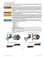
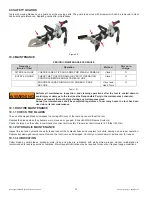
7.2 CUTTING
Rotating the control valve actuator regulates the hydraulic
fl
ow rate and power delivered to the tool. Turning the control valve actuator
to the end stops provides maximum hydraulic
fl
ow rate and power.
Figure 7.2

