background image


Installation & Operation Manual 

SAF-X


01.2022


 /

001301

-

910101


5.


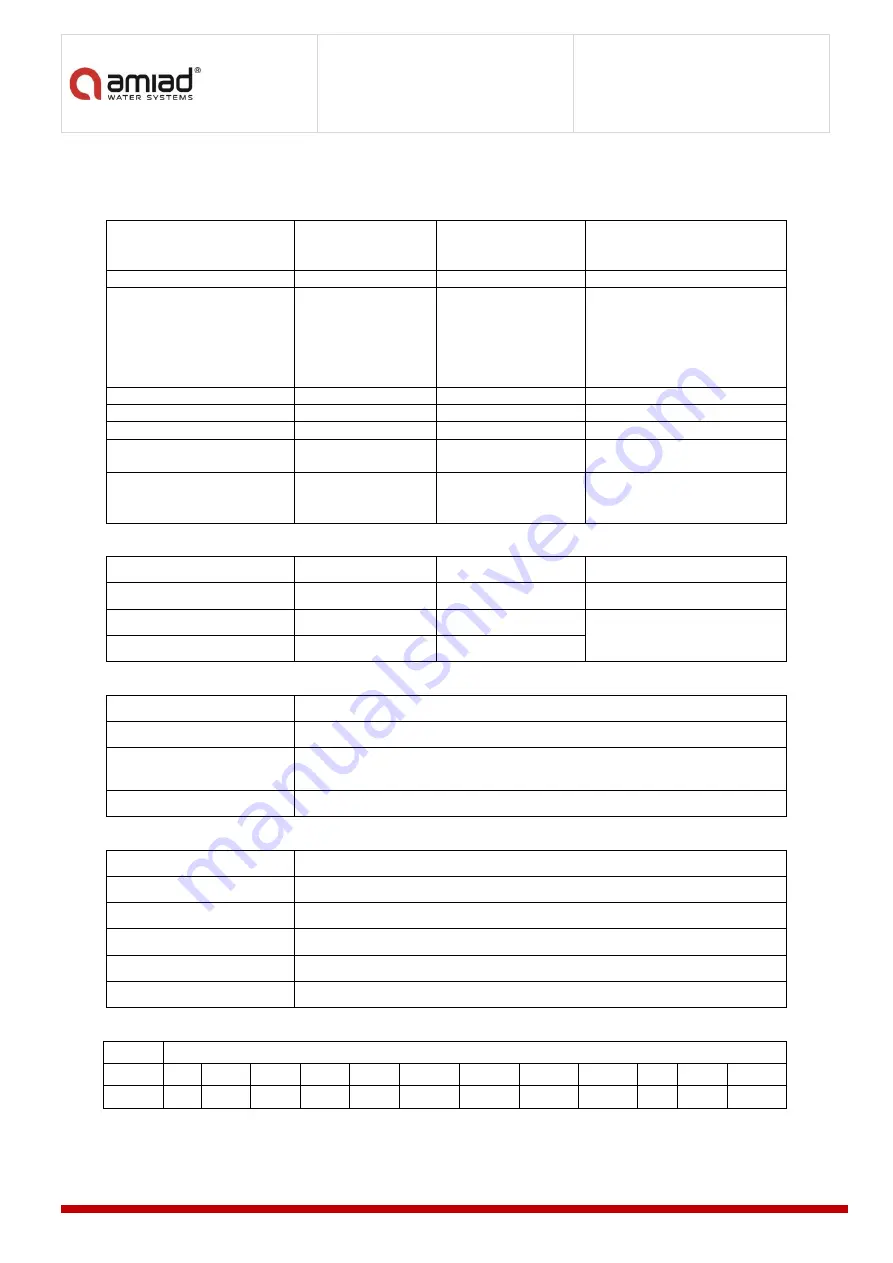
Technical Specifications SAF-X 3000 

General 


Maximum flow rate 

160 m

3

/hr 

700 gpm 

Consult manufacturer for 
optimum flow depending on 
filtration degree & water quality. 

Design Pressure 

10 bar(g) 

150 psi 


Min. Operating pressure 

2.0 bar(g) 

30 psi 

Pressure is critical during the 
flushing cycle.  
Consult manufacturer for the 
required values according to 
filtration degree and operation 
conditions. 

Temperature Min / Max 

4

0

 / 50

0

39.2

0

 / 122

0


Filtration area   

3000 cm

2


465 in

2


Inlet/Outlet diameter 

80,100,150 mm 

3", 4", 6" 

Flange standards as per request. 

Filter housing 

250 mm 

10" 

Epoxy-coated steel, or other on 
request. 

Weight: empty / Operation  

80 mm = 118/188 Kg 

100 mm = 121/191 Kg 
150 mm = 126/196 Kg 

3" = 260/414 lb. 
4" = 266/420 lb. 
6" = 277/431 lb. 


Flushing Data 


Exhaust valve 

50 mm 

2" 


Flushing cycle time 

20 seconds 

20 seconds 


Reject volume per cycle 

78 liter 

20 gallon 

STD Nozzle  

at 2.5 bar/35 psi 

Minimum flow for flushing 

14 m3/h 

62 gpm 

Control and Electricity 


Control voltage 

120 & 24 VAC or 24VDC  

Electric motor 

1/4 HP (0.18 kW) 50/60 Hz, 

Rated operation Voltage 

3 phase 208/230/380/400/415/460/575 Volt 50/60 Hz  

Single phase, 120/240 Volt 50/60 Hz  

Current consumption 

0.6 Amp. (see electrical diagram for specific values)  

Construction Materials 


Filter Housing and Lid 

Epoxy-coated carbon steel 37-2 (Stainless Steel 316 available on request). 

Screens 

Stainless Steel 316 

Cleaning mechanism 

Stainless Steel 316, POM, PVC 

Exhaust valve 

Epoxy-coated cast iron, Natural Rubber 

Seals 

Synthetic Rubber 

Control 

Aluminum, Brass, Stainless Steel, PVC 

Standard Filtration Degrees 


Stainless Steel Weave-wire Screen 

micron 

800 

500 

300 

200 

130 

100 

80 

50 

40 

30 

20 

10 

mm 

0.8 

0.5 

0.3 

0.2 

0.13 

0.1 

0.08 

0.05 

0.04 

0.0

0.02 

0.01 

Summary of Contents for SAF X 1500

Page 1: ...t Contains Amiad Confidential Information Copying and Distributing This Document are Strictly Prohibited Installation Operation Maintenance Instructions SERIAL NUMBER ORDER NUMBER CATALOG NUMBER TESTED BY SAF X Filters ...

Page 2: ... Specifications SAF X 3000 9 6 GA Drawing 4 SAF X 3000 available also with 3 and 6 connections 10 7 Technical Specifications SAF X 4500 11 8 GA Drawing 6 SAF X 4500 available also with 4 and 8 connections 12 9 Description of Filter Operation 13 10 Installation Instructions 15 11 Commissioning 18 12 Part Schedule 20 13 Spare parts Kits 24 14 Parts Drawings 25 15 Maintenance 30 16 Troubleshooting 37...

Page 3: ...nfidential nature of and or privilege in the file enclosed is not waived or lost as a result of a mistake or error in this file If you received this file in error please notify Amiad immediately at info amiad com This document does not replace any certified drawing procedure or information provided by Amiad in reference to a specific customer site or project Amiad assumes that all users understand...

Page 4: ...uture treatments and safe maintenance operations The user should arrange suitable lighting at the area of the filter to enable good visibility and safe maintenance The user should arrange suitable platforms ladders and safety barriers to enable easy and safe access to the filter without climbing on pipes and other equipment The user should verify that any platform barrier ladder or other such equi...

Page 5: ...et port Please note that the maximum working pressure indicated at the filter s specifications table includes the pressure caused by fluid hammer and pressure surge effects Civil Engineering Make sure that the filter installation is done by a qualified technician Make sure that any civil engineering work at the installation site such as construction lifting welding etc is done by qualified workers...

Page 6: ...e slippage electrification or damage to the equipment caused by moisture While using lifting equipment make sure that the filter or the lifted part is chained securely and in a safe manner Do not leave lifted equipment if there is no necessity Avoid working below lifted equipment Wear a safety helmet goggles gloves and any other personal safety equipment required by the local standards and regulat...

Page 7: ...260 392 lb Flushing Data Exhaust valve 50 mm 2 Flushing cycle time 20 seconds 20 seconds Reject volume per cycle 39 liter 10 gallon STD Nozzle at 2 5 bar 35 psi Minimum flow for flushing 7 m3 h 31 gpm Control and Electricity Control voltage 120 24 VAC or 24VDC Electric motor 1 4 HP 0 18 kW 50 60 Hz Rated operation Voltage 3 phase 208 230 380 400 415 460 575 Volt 50 60 Hz Single phase 120 240 Volt ...

Page 8: ...8 SAF X 01 2022 001301 910101 Installation Operation Manual 4 GA Drawing 3 SAF X 1500 available also with 2 and 4 connections ...

Page 9: ... 277 431 lb Flushing Data Exhaust valve 50 mm 2 Flushing cycle time 20 seconds 20 seconds Reject volume per cycle 78 liter 20 gallon STD Nozzle at 2 5 bar 35 psi Minimum flow for flushing 14 m3 h 62 gpm Control and Electricity Control voltage 120 24 VAC or 24VDC Electric motor 1 4 HP 0 18 kW 50 60 Hz Rated operation Voltage 3 phase 208 230 380 400 415 460 575 Volt 50 60 Hz Single phase 120 240 Vol...

Page 10: ...10 SAF X 01 2022 001301 910101 Installation Operation Manual 6 GA Drawing 4 SAF X 3000 available also with 3 and 6 connections ...

Page 11: ... 8 332 528 lb Flushing Data Exhaust valve 50 mm 2 Flushing cycle time 20 seconds 20 seconds Reject volume per cycle 117 liter 30 gallon STD Nozzle at 2 5 bar 35 psi Minimum flow for flushing 21 m3 h 93 gpm Control and Electricity Control voltage 120 24 VAC or 24VDC Electric motor 1 4 HP 0 18 kW 50 60 Hz Rated operation Voltage 3 phase 208 230 380 400 415 460 575 Volt 50 60 Hz Single phase 120 240 ...

Page 12: ...12 SAF X 01 2022 001301 910101 Installation Operation Manual 8 GA Drawing 6 SAF X 4500 available also with 4 and 8 connections ...

Page 13: ... of suspended solids and therefore it is not cleaned automatically Self cleaning process The SAF X initiates the self cleaning process when either the pressure differential across the fine screen reaches a pre set value or the flush timer reaches its preset timed interval The exhaust valve opens creating high velocity suction force at the scanner s nozzles edges which vacuums the filter cake from ...

Page 14: ...esult of any of the following 1 Pressure Differential 2 Time Interval 3 Manual Start from local control panel 4 Manual Start from remote control system Pressure Differential Operation There are three options for DP measuring a Pressure Differential Switch fixed or adjustable b Analog Differential Pressure Transmitter c 2 X Pressure Transmitters one connected to the filter inlet and one to the outl...

Page 15: ... Pressure Gauge It is highly recommended to have pressure indicators upstream and downstream of the filter 3 Flush pipe arrangement a Diameter of the flush line should be 2 minimum and should be designed to create minimal resistance with the flushing flow rate Check the technical specifications for the relevant value b If length of the flushing line is more than 5m 16 ft changing it to 3 is recomm...

Page 16: ...sure to review and follow the relevant safety instructions on page 4 of this document 1 Control Panel Amiad Control panels are suitable for outdoor installation however dry and protected place is always preferred Eye contact between the control panel and the filter is highly recommended 2 Motor wiring Use long enough cable to allow the drive unit to be removed and placed near the filter for mainte...

Page 17: ...trician 4 The motor must stop when the limit switch plate reaches the limit switch opening the NC circuit 5 Operate a dry flushing cycle by pressing on the TEST push button Check that the flushing cycle runs as described in the Self cleaning process paragraph in this manual 6 Open the inlet valve to the filter leaving the outlet valve closed or with an open by pass valve This will keep the flow th...

Page 18: ...ge It is possible to run the motor manually but it will not run automatically 8 Operate momentarily the motor Outward upward and verify that scanner is indeed moving Out CCW Switch rotation direction of the motor if required 9 Operate momentarily the motor Inward downward and verify that scanner is indeed moving in CW Switch rotation direction of the motor if required 10 Verify that both Limit Swi...

Page 19: ...nd turn it to work according to DP with time backup of 6 hours 8 Simulate HDP and HHDP conditions and verify the reaction of the control system For details refer to the Control System Section 9 Follow and study the system functioning for fine tuning of the flushing interval and DP set points Note Not all control features are available in all control panels types and models For details refer to the...

Page 20: ...5 000052 PIN COTTER 3 64 X 5 8 MM 2 S ST 316 38 760106 000010 EXTERNAL RETAINING RING 25 MM DIN 471 1 S ST 316 39 710101 001613 DRIVE SHAFT COVER 1 PP 40 780102 000020 2 VICTAULIC CONNECTOR 1 C ST 41 780101 001671 2 GROOVED ELBOW 1 DUCTILE IRON 42 780101 000822 2 GALVANIZED M CONNECTOR 1 GALVANIZED CS 100 770102 000176 O RING 2 452 70 SHORE 1 NBR 101 770104 000403 SAF X SEALING SLEEVE HYDRAULIC SE...

Page 21: ...0034 1 4 M F FINGER FILTER PLASTIC BLACK 1 VARIOUS 306 730104 000232 2 WAY BALL VALVE 3 4 M F 1 NICKEL PLATED BRASS 307 720502 000036 CONTROL TUBE 5 16 BLACK 6 PA 308 720501 000213 CONNECTOR 5 16 X1 8 68F 2 BRASS 309 730108 000113 AIR RELEASE VALVE D 040 P 3 4 BSPT 1 PP 310 700190 002336 MANOMETER VALVE 1 4 W DRAIN ASSY 1 VARIOUS 311 720202 000019 GEAR RMI50 63 B5 1 28 SITI MT 5010 1 VARIOUS 312 7...

Page 22: ... PT4X20 8 S ST 316 SAF X 3000 ITEM NO CAT NO DESCRIPTION QTY MATERIALS 11 700190 006224 SCANNER ASSEMBLY FOR SAF X 3000 INJECTED NOZZLES 1 VARIOUS 12 710103 011319 SUCTION SCANNER SHAFT SAF X 1 S ST 316 13 760105 000098 DOWEL PIN 6X36 DIN7 1 S ST 316 14 710103 002501 PLUG 8MM SAF FOR SCANNER 1 POM 15 710102 004617 SAF X 3000 SUCTION SCANNER S ST316 NON SLN 1 S ST 316 16 17 710101 000922 MOLDED SCA...

Page 23: ...710103 011319 SUCTION SCANNER SHAFT SAF X 1 S ST 316 13 760105 000098 DOWEL PIN 6X36 DIN7 1 S ST 316 14 710103 002501 PLUG 8MM SAF FOR SCANNER 1 POM 20 710103 002103 SLN SPRING SEAT 4 POM 21 760107 000049 SLN SPRING 4 S ST 302 22 710103 002106 SLN HOUSING FOR SAF 4 S ST 316 23 710103 002105 TIGHTENING NUT FOR SAF SLN 4 POM 24 710103 002104 SLN CAP FOR SAF 4 HMPE 107 710101 001281 SLN SEAL 16MM TPU...

Page 24: ...0 STD SCANNER NOZZLES PREVENTIVE MAINTENANCE ONE YEAR 700194 000055 SAF X 4500 STD SCANNER NOZZLES PREVENTIVE MAINTENANCE ONE YEAR Each Kit contains the following items SLN SCANNER PREVENTIVE MAINTENANCE ONE YEAR QTY PER SAF X MODEL ITEM NO CAT NO DESCRIPTION 1500 3000 4500 26 700190 006190 SAF SHAFT SEALING ASSEMBLY 1 1 1 24 108 700190 002400 SLN CAP ASSEMBLY O RING 2 4 6 107 710101 001281 SLN SE...

Page 25: ...SAF X 01 2022 001301 910101 25 14 Parts Drawings Item 18 SLN Suction Scanner used for fine filtration 50 and below Item 11 STD Non SLN Suction Scanner used for 80 to 800 micron applications Check which one is relevant for your case ...

Page 26: ...26 SAF X 01 2022 001301 910101 Installation Operation Manual Details on Page 35 Details on Page 35 Details on Page 35 ...

Page 27: ...Installation Operation Manual SAF X 01 2022 001301 910101 27 ...

Page 28: ...28 SAF X 01 2022 001301 910101 Installation Operation Manual ...

Page 29: ...tallation Operation Manual SAF X 01 2022 001301 910101 29 Item 11 STD Non SLN Suction Scanner used for 80 to 800 micron applications Item 18 SLN Suction Scanner used for fine filtration 50 micron and below ...

Page 30: ...k bolts to avoid openings due to vibration Cat No 780201 000031 ML 2 Silicone Grease MOLYKOTE R PG 21 PLASTISLIP GREASE Used for O ring lubrication Cat No 760190 000127 ML 3 NON MELT GREASE for lubrication of drive shaft and motor key Cat No 760190 000097 ML 4 Silicone Spray H1 for lubrication of seals and gaskets Cat No 780202 000012 ML 5 Anti Seize Grease WEICON ASW 450 prevent seizing of stainl...

Page 31: ...g frequency depends on flow rate and water quality Suspended Solids type load and Chemistry Therefore the frequency of scheduled routine maintenance activities should be determined during the commissioning and first few months of operation It is essential to follow the flushing frequency and the trend of DP build up to react on time when an un usual change is recognized It is recommended to includ...

Page 32: ...enance are available as per the following table CAT NO DESCRIPTION 700194 000050 SAF X 1500 SLN SCANNER PREVENTIVE MAINTENANCE ONE YEAR 700194 000051 SAF X 3000 SLN SCANNER PREVENTIVE MAINTENANCE ONE YEAR 700194 000052 SAF X 4500 SLN SCANNER PREVENTIVE MAINTENANCE ONE YEAR 700194 000053 SAF X 1500 STD SCANNER NOZZLES PREVENTIVE MAINTENANCE ONE YEAR 700194 000054 SAF X 3000 STD SCANNER NOZZLES PREV...

Page 33: ... treatment as long as they do not contain gypsum The common ones are Hydrochloric acid HCL Sulfuric acid H2SO4 It is recommended to dilute the acid to a concentration of about 2 in which case the acid is still effective but is less dangerous Remove the seals from the Screen cylinder and soak it in the solution for 10 20 minutes depending on the amount and kind of precipitates The Screen should the...

Page 34: ...ock the screen in its place and prevent it from turning during flushing Verify that the hydraulic seal is mounted on the Coarse Screen Assembly 8 Lubricate it with some silicone lubricant ML 2 or ML 4 Insert the Coarse Screen Assembly 8 and verify it is properly fits Verify that the Lid O ring 100 is in place Close the filter front lid and tighten is bolts 200 in even manner Re connect the power a...

Page 35: ... disconnecting the cable 5 At this stage it is possible to adjust the Limit Switches 315 position by manually turning the drive shaft by means of 17 mm wrench 6 Re assemble in reverse order Verify the existence of the drive shaft key Lubricate the drive shaft 32 and gearbox 311 with Multi Purpose Grease ML 03 Limit Switches adjustment 1 Remove the drive unit 311 312 as described above 2 Slightly r...

Page 36: ...tallations which are exposed to freezing conditions during winter while the filter is not in use If the filter supposed to be in operation under freezing risk conditions thermal isolation and heat tracing must be considered 1 Close isolation outlet valve and initiate a few flush cycles 2 Close isolation inlet valve and open the Drain valve 3 Disconnect power at the middle of a flush cycle so shaft...

Page 37: ...ossible to work according to short time intervals Motor Overload Too high mechanical resistance 1 Remove the side covers and check for mechanical damages 2 Remove the drive unit and check if the motor is running without load 3 Try turning the drive shaft by means of a proper wrench 4 Reset the motor protector and check the current consumption If problem cannot be solved 1 Disassemble the filter ac...

Page 38: ...a representative of Amiad 8 This Warranty will not apply to damaged or defective products resulting from or related to i Fire flood power surges or failures or any other catastrophe and or unforeseen occurrence such as but not limited to those for which the Buyer is customarily insured for or any force majeure events ii Fault abuse or negligence of the Buyer iii Intake water not meeting the agreed...

Page 39: ...lil Elyon 1 1233500 Israel Tel 972 4690 9500 Fax 972 48141159 Email info amiad com European Authorised Representative for CE Obelis s a Bd Général Wahis 53 1030 Brussels Belgium Tel 32 2732 5954 Fax 32 27326003 Email mail obelis net EU Declaration of Conformity https www amiad com certificatesDownload asp ...

Reviews: