


AMG Systems Ltd. reserves the right to make changes to this document without
notice. The information herein is believed to be accurate. No responsibility is
assumed by AMG for its use.
Page 9 of 9
AMG2783A-1-DR-
CWDMn,m -SF Instruction
Sheet D15185-00
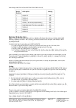
Secondary Channel TX Card (Zero Channel Video TX Card)
Switch
Position
Description
Setting
1
Not Used
OFF
2
Not Used
OFF
3
Not Used
OFF
4
Primary / Secondary Board Setting
OFF
5
Dual Redundant / Not dual redundant
ON
6
Not Used
OFF
7
Not Used
OFF
8
Not Used
OFF
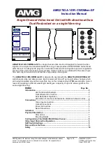
Removal From the Case
Note: -
The 2700 PCB’s are static sensitive. Handle with proper care and use normal electrostatic
discharge (ESD) procedures. Use properly grounded protection (for example, wrist stamps) when
handling the PCB.
In order to remove the case (to access SW1 and SW2)
1.1. Loosen and remove the four screws on the top and bottom of the unit’s rear panel.
1.2. Slide the PCB assembly connected to the rear panel out of the case.
1.3. Ensure that the optical fibre is not trapped.
1.4. The Primary Channel TX card is the PCB which has the video input BNC attached through the
rear panel labelled CH1.
SW1 and SW2 can be found on the bottom right hand corner of each board and are labelled, close to
the rear panel. The switch position are labelled on the switch, switch position 1 is always the furthest
from the edge of the PCB.
When re-inserting the main PCB into the housing take care not to trap the optical fibre or the board
interconnection cables.
Fasten the rear panel with the screws.
Safety
The 2700 series of products uses a Class 1 laser system in accordance with EN 60825-2:2000 and as
such the optical power emitted from the optical connector is regarded as eye safe under all operating
conditions.
However it is always advisable to follow good practice when working with optical fibre systems. This
includes:
Do not stare with unprotected eyes or with any unapproved collimating device at fibre ends or
connector faces, or point them at other people.
Use only approved filtered or attenuating viewing aids
For other safety issues and advice on good practice associated with the optical fibres systems see EN
60825-2:2000 or your local safety officer.
There are no user serviceable parts within the AMG2700 products.
In case of problem or failure contact your local support centre or AMG Systems Ltd, Technical Support
Department on tel. +44 (0) 1767 600777 .
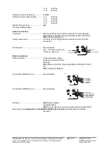
See unit data sheet for full specification.