AMG Systems AMG2783A-1-DR-CWDMnm-SF Instruction Manual Download Page 6

AMG Systems Ltd. reserves the right to make changes to this document without
notice. The information herein is believed to be accurate. No responsibility is
assumed by AMG for its use.

Page 6 of 9

AMG2783A-1-DR-
CWDMn,m -SF Instruction
Sheet D15185-00

n = 6

1490nm

n = 8

1610nm

Primary Channel Sensitivity................. -22dBm
Primary Channel Wavelength .............. n = 1

1510nm

n = 3

1550nm

n = 5

1470nm

n = 7

1590nm

Optical Through Loss .......................... 4dB
for unused wavelengths
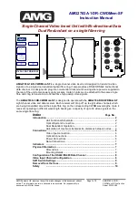
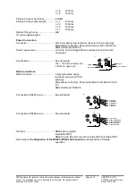
Power Connection

Connector ............................................2off removable screw terminal connector (3.5mm spacing)

Manufacturers Part No. Phoenix/Combicom MC1-5/2-ST-3.5
AMG Part No.G00047-00

Power requirement .............................. 12 volt to 16 volt DC @ 800mA combined current for both

connectors

Connections......................................... See schematic

+12 – 16 Volts on lower pin
0 Volts on upper pin

Data Connections

Data Connector ................................... 5 way removable spring

terminal connector (2.5mm
spacing)
Manufacturers Part No. Phoenix/Combicom FK-MC-0.5/5-ST-
2.5
AMG Part No G15098-00

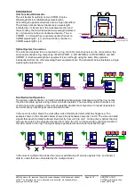
Connections RS422 4 wire .................. See schematic

Connections RS485 4 wire .................. See schematic

Protocol................................................ RS485 2wire (switch

selectable SW2)
RS422 4 wire Bus’ed or point to point (switch selectable SW1)
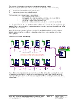
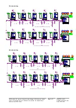
See below for

Configuration of the RS485 / RS422 data channel

and description of tristate

operation

OPTO IN

D
A
T
A

CH 8

CH 4

OPTO IN

0 Volts

+12 – 16 Volts

0 Volts

+12 – 16 Volts


OPTO IN

D
A
T

A


CH 8

CH 4

OPTO IN

Pin 5 – Ground
Pin 4 – Data Out –
Pin 3 – Data Out +
Pin 2 – Data In –
Pin 1 – Data In +


OPTO IN

D
A
T
A


CH 8

CH 4

OPTO IN

Pin 5 – Ground
Pin 4 – No Connection
Pin 3 – No Connection
Pin 2 – Data In/Out –
Pin 1 – Data In/Out +

Summary of Contents for AMG2783A-1-DR-CWDMnm-SF

Page 1: ...operate with the AMG2784 DR CWDMnm SF eight channel video and data receiver Each receiver will drop off up to eight video channels which are being transmitted around the single fibre ring on the corr...

Page 2: ...aks the receiver will still drop off all video signals from and transmit data to nodes that are not isolated by the multiple breaks 1 2 3 8 1 3 8 2 2783A 1 DR CWDM1 2 SF A M G PRIMARY OPTO SYNC TX OO...

Page 3: ...4 dB loss 5 6 7 8 4 3 2 1 2783A 1 DR CWDM1 2 SF A M G PRIMARY OPTO SYNC TXO ORX SECONDARY OPTO SYNC TXO ORX VIDEO PRESENT CH1 O ORX CH1 O ORX DATA PRESENT 1 CHVIDEO INSERT DATA TX RX POWER O POWER O...

Page 4: ...O ORX DATA PRESENT 1 CH VIDEO INSERT DATA TX RX POWER O POWER O 2783A 1 DR CWDM3 4 SF AM G PRIMARY OPTO SYNC TX O O RX SECONDARY OPTO SYNC TX OO RX VIDEO PRESENT CH1 O ORX CH1 O ORX DATA PRESENT 1 CH...

Page 5: ...RX POWER O POWER O 2783A 1 DR CWDM5 6 SF A MG PRIMARY OPTO SYNC TX OO RX SECONDARY OPTO SYNC TX O ORX VIDEO PRESENT CH1 O ORX CH1 O O RX DATA PRESENT 1 CH VIDEO INSERT DATA TX RX POWER O POWER O 2783...

Page 6: ...for both connectors Connections See schematic 12 16 Volts on lower pin 0 Volts on upper pin Data Connections Data Connector 5 way removable spring terminal connector 2 5mm spacing Manufacturers Part N...

Page 7: ...corresponding data input This represents the data signals being transmitted on the optical fibre Data Present RX Green logic one present on the corresponding data output Red logic zero present on the...

Page 8: ...on the video input can be inserted on one of eight video channels transmitted on the optical fibre The input channel number is set by SW1 on the primary channel TX board See below for removal of the...

Page 9: ...SW1 and SW2 can be found on the bottom right hand corner of each board and are labelled close to the rear panel The switch position are labelled on the switch switch position 1 is always the furthest...

Reviews: