


AMG Systems Ltd. reserves the right to make changes to this document without
notice. The information herein is believed to be accurate. No responsibility is
assumed by AMG for its use.
Page 8 of 9
AMG2783A-1-DR-
CWDMn,m -SF Instruction
Sheet D15185-00
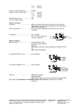
The data input for both the RS485 and the RS422 modes detects a tristate-input condition by
monitoring the differential voltage level across the input. A differential level below 500mV positive or
negative will be detected as a tristate condition. A level above 500mV positive or negative will be
detected as a logic 1 or logic zero respectively.
It is important therefore to terminate the RS485
bus or the RS422 input bus using 120ohms if a pre-bias is present on the RS485 or RS422 bus.
A large number of third party equipment manufacturers apply a pre-bias on their RS485 bus. This pre-
bias is applied by pulling one arm of the RS485 bus high (+5 volts) and the other ar m low (0 volts)
using high value resistors within the third party equipment. In order to ensure that a tri-state condition
is detected by the AMG2700 equipment, then these resistors should have a value above 1kohm.
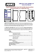
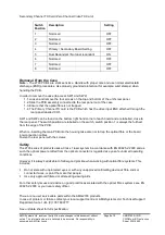
Video input channel configuration
The video present on the video input can be inserted on one of eight video channels transmitted on
the optical fibre. The input channel number is set by SW1 on the primary channel TX board. (See
below for
removal of the PCB
and access to SW1)
The channel number is set by the SW1 switch positions 1 to 3 – see below.
Video Input Channel Number
SW1
position 1
SW1
position 2
SW1
position 3
1
OFF
OFF
OFF
2
ON
OFF
OFF
3
OFF
ON
OFF
4
ON
ON
OFF
5
OFF
OFF
ON
6
ON
OFF
ON
7
OFF
ON
ON
8
ON
ON
ON
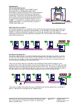
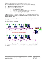
It is normal to set each AMG2700 insert unit to a different channel number. If a number is used twice
the second unit connected ‘down stream’ on the primary optical route will ‘over-write’ the first unit and
the video signal will be lost.
The channel number is only required to be set on SW1 on the primary channel TX card. Positions 1 to
3 on SW1 on the secondary channel TX card do not effect the operation of the equipment.
SW1 Switch Settings
Only switch positions 1 to 3 should be set by the user, all other switch settin gs are set at the factory as
follows:
Primary Channel TX Card (Single Channel Video TX Card)
Switch
Position
Description
Setting
1
Video channel configuration
See above
2
Video channel configuration
See above
3
Video channel configuration
See above
4
Primary / Secondary Board Setting
ON
5
Dual Redundant / Not dual redundant
ON
6
Not Used
OFF
7
Not Used
OFF
8
On board data / Separate data card
ON