background image


iii 

Important Safety Instructions


Before applying power to the system, verify that your product is configured properly for your 
particular application. 


WARNING


Hazardous voltages may be present when covers are removed. Qualified 
personnel must use extreme caution when servicing this equipment.  
Circuit boards, test points, and output voltages also may be floating above 
(below) chassis ground.


WARNING


The equipment used contains ESD sensitive ports. When installing 
equipment, follow ESD Safety Procedures. Electrostatic discharges might 
cause damage to the equipment. 

Only 

qualified personnel

 who deal with attendant hazards in power supplies, are allowed to perform 

installation and servicing. 

Ensure that the AC power line ground is connected properly to the Power Rack input connector or 
chassis. Similarly, other power ground lines including those to application and maintenance 
equipment 

must 

be grounded properly for both personnel and equipment safety. 

Always ensure that facility AC input power is de-energized prior to connecting or disconnecting any 
cable. 

In normal operation, the operator does not have access to hazardous voltages within the chassis. 
However, depending on the user’s application configuration, 

HIGH VOLTAGES HAZARDOUS TO 

HUMAN SAFETY

 may be normally generated on the output terminals. The customer/user must 

ensure that the output power lines are labeled properly as to the safety hazards and that any 
inadvertent contact with hazardous voltages is eliminated. 

Guard against risks of electrical shock during open cover checks by not touching any portion of the 
electrical circuits. Even when power is off, capacitors may retain an electrical charge. Use safety 
glasses during open cover checks to avoid personal injury by any sudden component failure. 

Neither AMETEK Programmable Power Inc., San Diego, California, USA, nor any of the subsidiary 
sales organizations can accept any responsibility for personnel, material or inconsequential injury, 
loss or damage that results from improper use of the equipment and accessories.


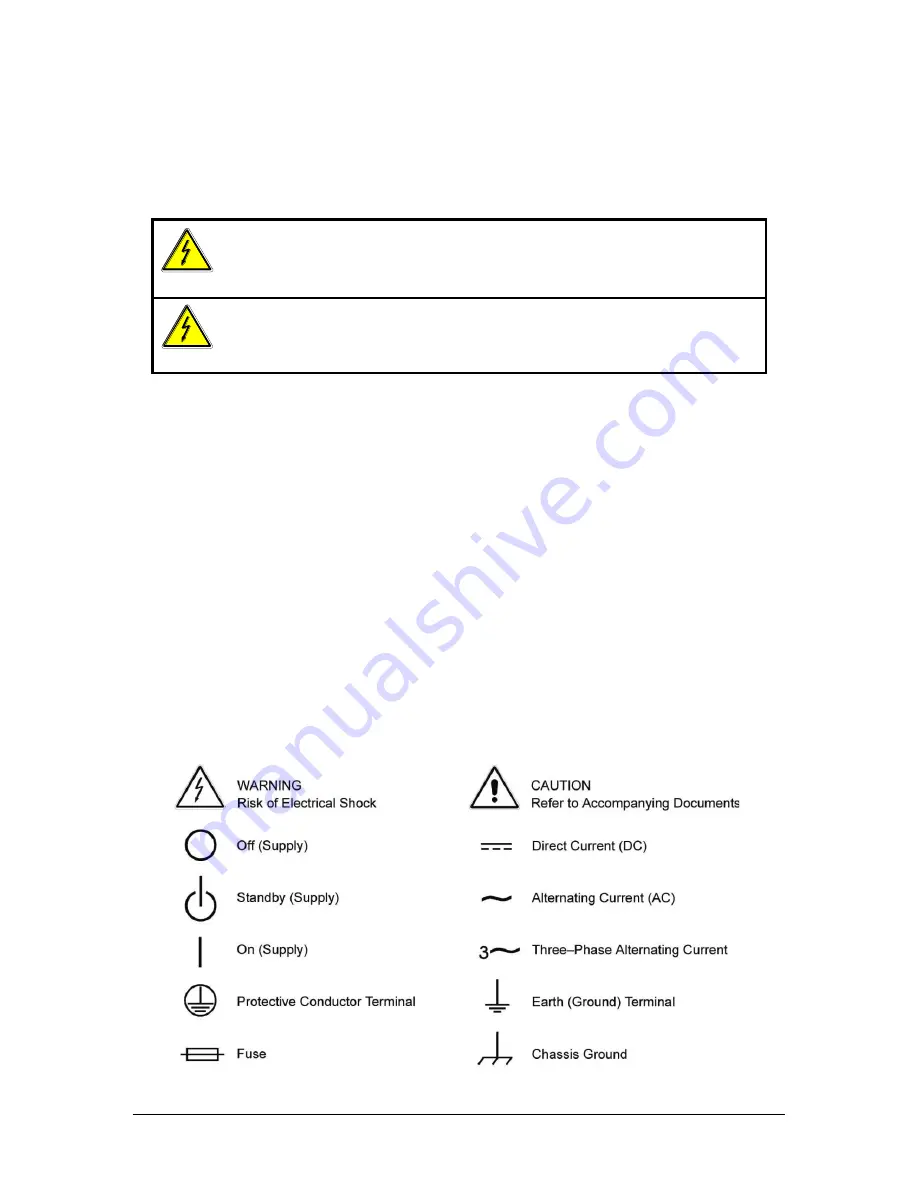
SAFETY SYMBOLS 


Summary of Contents for GUPS 2400A-107

Page 1: ...Fax 858 458 0267 Email Domestic Sales domorders sd ametek com International Sales intlorders sd ametek com Customer Service service ppd ametek com Web www programmablepower com GLOBAL UNINTERRUPTIBLE...

Page 2: ......

Page 3: ...ly Notice of Copyright Global Uninterruptible Power Supply Operation Manual 2010 AMETEK Programmable Power Inc All rights reserved Exclusion for Documentation UNLESS SPECIFICALLY AGREED TO IN WRITING...

Page 4: ...ii This page intentionally left blank...

Page 5: ...nnel and equipment safety Always ensure that facility AC input power is de energized prior to connecting or disconnecting any cable In normal operation the operator does not have access to hazardous v...

Page 6: ...uctions of AMETEK is opened modified or disassembled in any way without AMETEK s consent or is used in combination with items articles or materials not authorized by AMETEK The Buyer may not assert an...

Page 7: ...Installation 2 2 2 4 Air Intake and Exhaust 2 2 2 5 Input Output Connectors 2 2 2 6 Wire Gauge Selection 2 6 SECTION 3 OPERATION 3 1 3 1 Introduction 3 1 3 2 Control and Indicator Panel 3 1 3 2 1 Ind...

Page 8: ...shooting 4 2 LIST OF FIGURES Figure 2 1 GUPS 2400A 107 Front View 2 3 Figure 2 2 GUPS 2400A 107 Rear View 2 4 Figure 2 3 GUPS 2400A 107 Dimensions Top Side and Front Views 2 5 Figure 3 1 GUPS 2400A 10...

Page 9: ...input and output connections are made at the rear panel Cooling air is drawn in through a filter on the front panel and exhausted out the rear panel Operational and input output power status is indica...

Page 10: ...imum low line voltage 232V minimum high line voltage Battery to AC Crossover 169V maximum low line voltage 232V minimum high line voltage AC Input Voltage Unbalance 7V RMS maximum difference in line v...

Page 11: ...orm a visual inspection of the shipping container prior to accepting the package from the carrier If extensive damage is evident a description of the damage should be noted on the carrier s receipt an...

Page 12: ...take is located on the front panel of the instrument and the exhaust is through the rear panel Care must be taken not to block the air intake and exhaust No special vertical separation is required whe...

Page 13: ...Installation GUPS 2400A 107 Operation Manual 2 3 Figure 2 1 GUPS 2400A 107 Front View...

Page 14: ...Installation 2 4 GUPS 2400A 107 Operation Manual Figure 2 2 GUPS 2400A 107 Rear View...

Page 15: ...Installation GUPS 2400A 107 Operation Manual 2 5 Figure 2 3 GUPS 2400A 107 Dimensions Top Side and Front Views...

Page 16: ...ge and insulation properties are recommended for power source applications Avoid using published commercial utility wiring codes These codes are designed for the internal wiring of homes and buildings...

Page 17: ...e length in feet Vloss Maximum loss in volts permitted within cable SPECIAL CASE Should the Vloss requirement be very loose Ipeak may exceed the maximum amperes Column 2 In this case the correct wire...

Page 18: ...rom any source The differential voltage to other nearby conductors and Safety margins to accommodate degradations due to age mechanical abrasion and insulation migration caused by bending and temperat...

Page 19: ...control panel 3 2 1 Indicators AC INPUT Three green LED s that indicate the presence of line voltage at the AC input The indicators turn on when the line voltage is greater than 90V phase voltage grea...

Page 20: ...normal operating conditions and red when an over temperature shutdown occurs TEST A two color LED that indicates the results of the internal self test The LED blinks while a self test is in progress W...

Page 21: ...dible alarm will again be sounded 3 5 Control Signals The Data Alarm Port provides an interface to remote alarms or a host computer The control signals provide annunciation of the mode of operation co...

Page 22: ...Connectors The GUPS 2400A 107 has cylindrical metal shell connectors with bayonet coupling for all input output connections of power and signal All connectors are located on the rear panel Pin assign...

Page 23: ...power from the AC input and also recharge the battery with the battery charger 5 To turn OFF the output press the OUTPUT ON switch again the switch has a alternating ON OFF action The inverter will m...

Page 24: ...the effective surface area of the plates which reduces the available backup time Allowing the batteries to self discharge for too long may result in recharging problems or in battery degradation Stori...

Page 25: ...PS F Signal Ground Table 3 3 RS 232 Connector Pin Out 3 9 2 Software Interface The RS 232 interface firmware in the GUPS 2400A 107 has the following communication features Two sets of remote terminal...

Page 26: ...S 232 text data mode commands have been developed for a user interface utilizing a dumb terminal interface The text data mode commands provide formatted responses that include both the name of data pa...

Page 27: ...3 Output voltage readback calibration in Vout rdbk dvm 114 5 floating point format 3 9 4 3 Display Status Registers and A D Values Enter a command s lowercase S character to display the two 16 bit sta...

Page 28: ...age in hexadecimal Battery Bad Voltage Battery Shutdown Voltage Output Voltage Measurement scale factor in floating point Output Voltage Measurement 3 9 5 2 Provide Status Words and Hexadecimal A D Va...

Page 29: ...d 1 Alarm Sensed 2 Alarm Silence 0 Alarm Silence Not Enabled 1 Alarm Silence Enabled 3 Charger Status 0 Charger Not On 1 Charger On 4 Current Overload 0 Normal Operation 1 Current Overload 5 Battery S...

Page 30: ...ects the condition of the charger enabled logic of the GUPS 2400A 107 A binary value of 0 indicates that the charger is not on while a binary value of 1 indicates that the charger is on Current Overlo...

Page 31: ...ectifier slow start mode Equalization Charge Status Word 1 Bit 11 The Equalization Charge status bit indicates that the unit is in equalization charge enable mode A binary value of 0 indicates that th...

Page 32: ...tery 1 Running on AC Line 6 150 Overload Sense 0 Normal Operation 1 150 Overload Detected 7 Float Timer Time out 0 Not Float Charging 1 Float Timer Time out 8 Wait to equalize 0 No Equalization Pendin...

Page 33: ...m shutdown mode Status Word 2 Bit 4 Reserved Running on AC Line Status Word 2 Bit 5 The Running on Line status bit indicates that the unit is operating on the AC input A binary value of 0 indicates th...

Page 34: ...ified input range while a binary value of 1 is not within the specified input range Delayed Event Flag Status Word 2 Bit 12 The Delayed Event Flag status bit indicates the status of pending delayed ev...

Page 35: ...l number in any correspondence concerning this instrument DO NOT return the unit to the factory without prior authorization 4 3 Spare and Repair Parts When ordering spare parts or repair parts specify...

Page 36: ...indicator is illuminated red The filter is clogged Clean the filter if required The BATTERY indicator is illuminated red 1 Low battery voltage or 2 a defective battery 1 Recharge the battery or 2 repl...

Reviews: